 |
Start Process Method Plan
-
Click
Process Method Plan
 in the Process Definition toolbar.
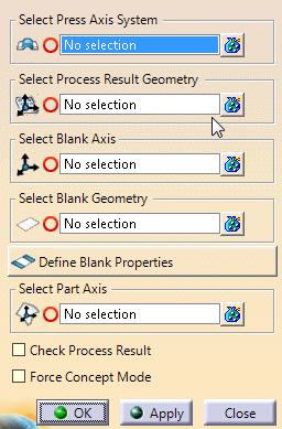
If the check box
Display detailed text in dialog in Tools/Options/Mechanical
Design/Die Face Design is cleared, the dialog box looks like this:
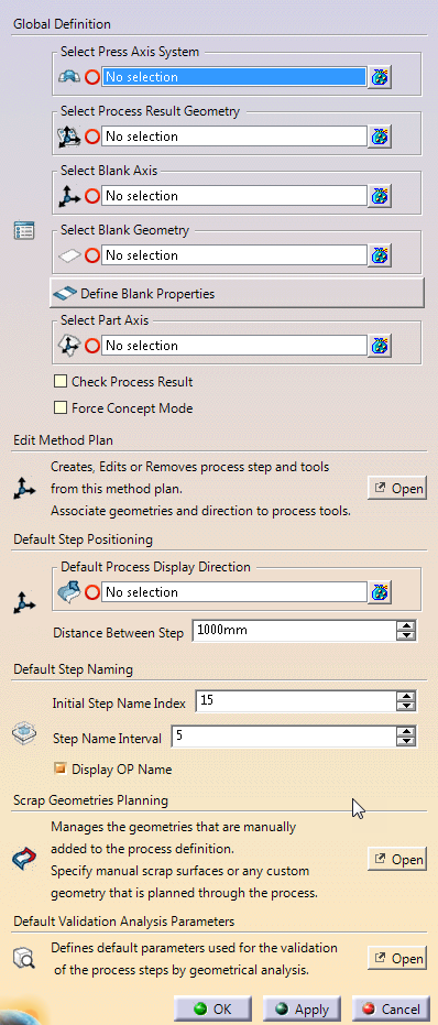
If the check box Display detailed text in dialog in
Tools/Options/Mechanical Design/Die Face Design is selected, the
dialog box looks like this:
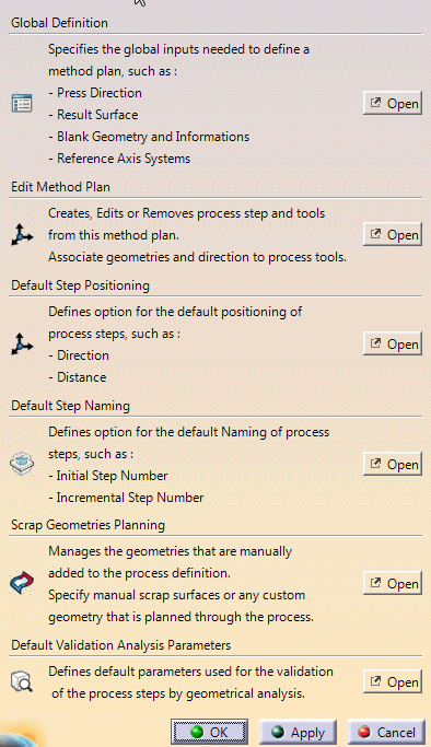
When required, click Open to access the
dialog boxes.
Define General Inputs and Parameters
-
Select the press
axis system to define the press direction of the method plan.
It is
usually the part axis system.
-
Select the process result geometry, that is the surface that represents
the output part of the whole process (Design Part).
-
Select the blank axis.
The blank axis is the reference to manipulate
the blank position. It is usually the press position translated to
center of gravity of the blank or output part.
If the blank axis is
not defined, Process Mathod Plan computes one from the press
direction and the center of gravity of the output geometry, or uses the
one defined as output geometry in the Part Positioning feature.
-
Select the blank geometry (Sketch of surface) to define the initial
sheet of metal geometry.
Click Blank Properties to edit
the blank partition that is automatically created from the
selected input.
-
Select the part axis.
An axis system is required for each domain of
the result geometry to define each part position independently from the
others in Process Step (Positioning section).
If the part axis is not defined, Process Method Plan computes
one from the press direction and the center of gravity of each part, or
uses the one defined as output geometry in the Part Positioning feature.
-
Select the Check Process Result check box to check that the
output geometry of Process Method Plan is the same as the
selected Process Result Geometry.
-
Select the Force Concept Mode check box to ignore all
specified detailed geometries and revert to the concept view of the
process.
An update is required after each modification.
Edit the Method Plan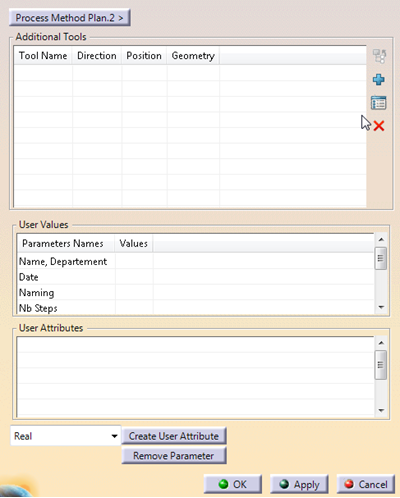
Add
 ,
edit ,
edit
 or remove
 tools.
 -
Enter user values. -
Create or remove user attributes.
Define the Default Step Positioning
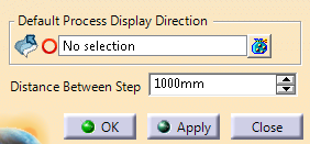
-
Define the process display direction, that is the
translation direction for each process step.
If the process display
direction is not defined, the X-Axis of the part is used. -
Enter the distance between step, that is the translation
value of each process step. Define the Default Step Naming
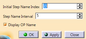
-
Enter the initial step name index. -
Enter the step name interval. -
Select or clear the Display OP Name check box. The
default index of a process step is defined by this formula:
Initial
Step Name Index + (Step numer -1)*Step Name Interval.
For example,
if
Initial Step Name Index = 15
Step Name Interval
= 5
the index of step
3 is : 15+(3-1)*5=25, i.e. OP25. Manage Scrap Geometries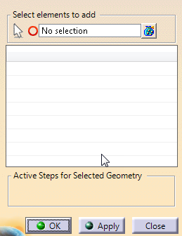
-
Select the elements to add.
For more information, see
Manage Scraps.
Define the Default Analysis Parameters
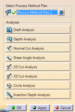
-
Click
an analysis button to configure it.
For more information, see
Configure Analyses. |