- Set the StrWeldPreparationSample file in the Project Resource Management for Structure Detailed Design workbench. The sample file is located at ..\..\startup\EquipmentAndSystems\Structure\StructuralCatalogs\Weld. This resource is available only in Structure Detailed Design.
- Open a structure containing plates, transverse bulkheads, seamed plates, stiffeners. There must be surface contact between the structural objects to create a weld.
-
Click Start > Equipment & Systems > Structure Discipline > Structure Detail System Design.
You are switched to Structure Detail System Design workbench. -
Click Weld
 in Structure Systems toolbar.
The Weld dialog box appears. -
Select the design unit containing structural objects to be welded.
The name of the selected design unit is displayed in the Design Unit box.
The Operated Element column lists the split objects that are being limited by another structural objects.
The Operating Element column lists the split objects limits structural objects.
At the selection of design unit, welds are not created. All the elements that can be welded with other elements are listed.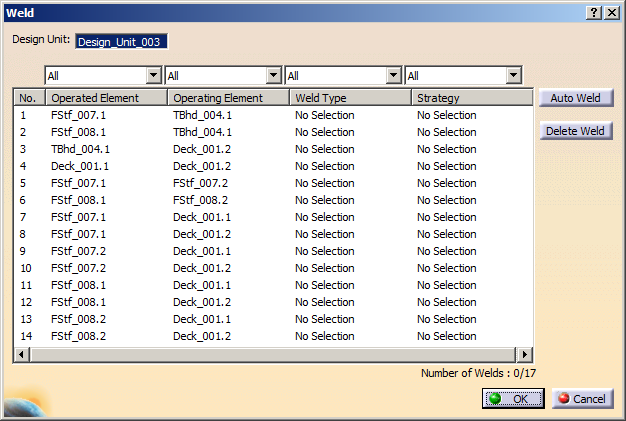
-
Optional: Apply filters to the operated and operating elements to create weld on the required elements.
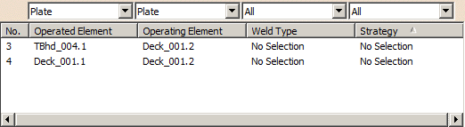

Different filters are available for each column. Using these filters, you can view only the required combination of operated and operating elements that have particular weld type and strategy. -
Select one or more rows in the dialog box and click Auto Weld.
The welds are created. The Weld Type column lists the weld type valid between the structural objects. The text file assigned in Project Resource Management evaluates the thickness or section of the operated and operating element and defines the weld type.- If the combination of thickness and section of the operated
and operating elements is not listed in the text file, the
following error message appears in the Weld Type and
Strategy column when you click Auto Weld.
Value not found: Check PRM definition.Check the text file assigned in StrWeldPreparationSample resource to refer combinations of thickness and section of the operated and operating elements for which welds can be created.
- When you apply filter and click Auto Weld, only the filtered objects get welded. Other objects are not considered for the weld operation.
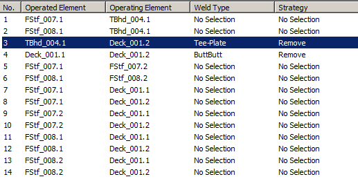
Depending on the connection between the structural objects, the different types of welds are:
- Tee-Plate: connection between plate and its limit.
- ButtButt: connection between two seamed plates.
- ButProfile: connection between two seamed profiles.
- Tee-Profile: connection between stiffener and its support.
- NONE: when a profile is limited by a plate, profile or surface.
- If the combination of thickness and section of the operated
and operating elements is not listed in the text file, the
following error message appears in the Weld Type and
Strategy column when you click Auto Weld.
-
To view the weld information, right-click in any row and select Define Weld.
The Weld Parameters dialog box appears displaying the information related to welded elements.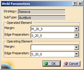
You can edit the margin and edge preparation value for operated and operating element. These values are predefined in text file assigned in the StrWeldPreparationSample resource in the Project Resource Management. -
Click OK to close the Weld Parameters dialog box.
-
If you want to delete any weld type, select the required rows and click Delete Weld.
The weld type and weld parameters are deleted. -
Click OK in the Weld dialog box.
A feature, WeldSet, is created in the specification tree. It carries the information related to welds created between the structural objects.
For each design unit, an independent weld set is created.
- When the piece parts are generated from design units containing a weld set, an option enables you to generate the coping feature for the weld information. For more information, refer to Structure Design User's Guide: Piece Parts: Generating Piece Parts.
- You can place the annotations (added material) and a weld symbol on the weld feature (for plate, stiffener and beam) in the 2D view. For more information, see Graphic Replacement of Plates and Annotation Text Style.