Digitized Morphing is done in two steps:
- Definition: A global deformation law is computed from the inputs.
- Application: This law is applied to the 3D inputs objects.
- The definition step is recomputed each time you update an element, even if only the application step is impacted.
Creating and using a deformation law as input to Digitized Morphing prevents this recomputation, thus sparing time.
The file of vectors used to compute the deformation is DeformationVectors01.txt in the samples directory.
-
Click 3D Deformation Law
 in the Realistic Shape Optimizer toolbar.
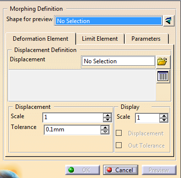
The 3D Deformation Law dialog box is displayed:
-
Since computing the deformation law is the first step of Digitized Morphing, proceed as explained in Digitized Morphing.
-
Click kbd>OK to validate.
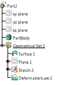
The deformation law is created under the specification tree.
-
Click the Digitized Morphing icon
 .
and select the element to deform.
.
and select the element to deform.
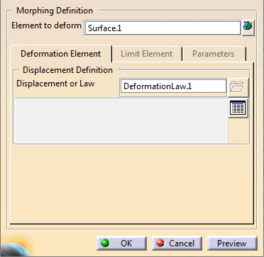
Select the deformation law you have created.
Since the deformation law already contains the required parameters, they are hidden from the dialog box.
-
Modify the element to deform as required.
-
Click OK to validate.
- If you deform a shape and a curve located above the shape, the logical link is lost.
- There is no guarantee that the result curve will be above the result shape.
![]()