When working in a CATProduct document, it is no longer necessary to copy and paste the bodies belonging to distinct parts before associating them. You can directly associate these bodies using the same steps as described in this task.
Structuring Your Design
Generally speaking, using Boolean Operations is a good way of structuring your part. Prior to designing, you can actually define the part's structure by associating a body containing geometry with empty bodies. Once these specifications are done, you can then concentrate on the geometry.
In this page, you will find the following information:
-
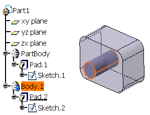
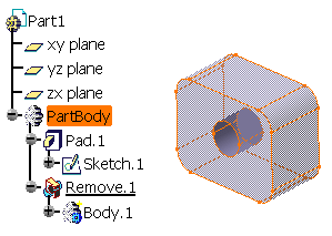
The part is composed of two bodies. To remove Body.1 from Part Body, select Body.1.

- Removing a set of bodies (multi-selected via the Ctrl key) is possible.
-
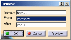
When the part is made of more than two bodies, the Remove dialog appears to let you determine the operation you wish to perform. By default, the application proposes to remove the selected body from the Part Body. To change that, just select another body from which you want to remove the selected body. The dialog will show the new selected body.

From V5R15 onward, you can:
-
get an idea of the result just by clicking the Preview button.
-
edit a Remove feature. To do so, you just need to double-click the feature and then select the new body to be removed.
Bodies You Can Use
-
Performing a Boolean operation using a set of bodies (multi-selected via the Ctrl key) is possible unless the bodies are located in ordered geometrical sets.
- Removing a body from a solid body and vice versa is possible. In that case, the second body you select remains at the same location in the specification tree once the Boolean operation is done. For reference information, refer to Mixed Boolean Operations.
-
From V5R16 onward, you can remove a body set in an ordered geometrical set (OGS) from another body set in the same ordered geometrical set or in a distinct one. Note that the different Boolean operations can be performed using dedicated contextual commands.
Depending on whether the Boolean operation interrupts the sequential construction of the geometry or not, the application behaves differently.No interruption of the sequential construction of the geometry
If there is no interruption of the sequential construction of the geometry, two cases are to be considered:
- if the bodies are set in the same OGS, the operation is performed and the second body selected is located below the Boolean operation node.
- if the bodies are set in distinct OGS, the operation is performed and the second body selected is moved below the Boolean operation node.
Interruption of the sequential construction of the geometry
If there is an interruption of the sequential construction of the geometry, two cases are to be considered:
- if the bodies are set in the same OGS, a warning message is issued informing you that the operation is going to be canceled: breaking the sequential construction of the geometry is not allowed when the operands belong the the same OGS.
- if the bodies are set in distinct OGS, a warning message is issued letting you choose between canceling the operation or going on. If you decide to continue, the second body you selected remains at its initial location in the tree.
Location of Bodies Once the Boolean Operation is Complete
Once a Boolean operation is done, the second body you selected is moved below the Boolean operation, as illustrated in the scenario above. However, there are exceptions to that rule:
-
Removing a body from a solid body and vice versa is possible. In that case, the second body you select remains at the same location in the specification tree once the Boolean operation is done. To see an example, refer to Mixed Boolean Operations.
-
If removing a body results in an interruption of the sequential construction of the geometry, the second body you selected to perform the Boolean operation remains at its initial location in the tree when the operation is complete. To see an example, refer to the Location of Bodies Once the Boolean Operation is Complete paragraph of Assembling Bodies.
Notes
-
You cannot re-apply the Assemble, Add, Trim, Intersect, Remove and Remove Lump commands to bodies already associated to other bodies. However, if you copy and paste the result of such operations elsewhere in the tree you can then use these commands.
-
Avoid using input elements that are tangent to each other since this may result in geometric instabilities in the tangency zone.
Optimizing Your Design
The Only Current Body option
![]() displays
only the features of the current body and greatly improves the application
performance whenever you edit these features. For more information, refer
to
Display in Geometry Area.
displays
only the features of the current body and greatly improves the application
performance whenever you edit these features. For more information, refer
to
Display in Geometry Area.
Interrupting Boolean Operations Computations
In case you made a mistake when performing a Boolean operation, you can
interrupt the feature computation launched after clicking OK,
when the computation requires a few seconds to perform.
In concrete terms, if the computation exceeds a certain amount of time, a
window appears providing a Cancel option. To interrupt the
operation, just click that Cancel button. This interrupts the
process and then displays an Update Diagnosis dialog box enabling you to
edit, deactivate, isolate or even delete the Boolean operation in progress.
This capability is available for any types of Boolean operations you are creating or editing.
Colors
When performing a mixed Boolean operation, the resulting geometry inherits the color of the first geometric entity selected.
