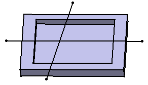
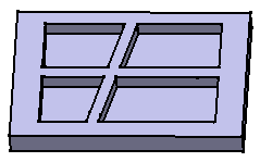
This task shows
you how to add thickness to a pad. The method described here is also valid
for pockets. In the Pad Definition
and Pocket Definition dialog
boxes, you can select Thick
check box to use options available under
Thin Pad.
To know how to obtain a thin solid from a stiffener, refer to
the task Stiffener.
You can create thin solids using the Shaft and Groove capabilities.
-
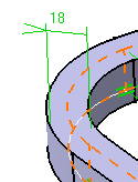
Enter 18mm as Thickness1 's value, and click Preview to see the result. A thickness has been added to the profile as it is extruded. The profile is previewed in dotted line.
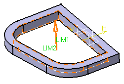
-
Enter 10mm as Thickness2 's value, and click Preview to see the result. Material has been added to the other side of the profile.
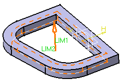
-
To add material equally to both sides of the profile, check Neutral fiber and click Preview to see the result.
The thickness you defined for Thickness 1 is evenly distributed: a thickness of 9mm has been added to each side of the profile.
Thin Pad options let you extrude profiles from networks
Using the Thin Pad options you can extrude profiles from networks.
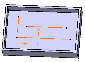
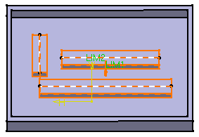
Keep in mind that the creation order of the different elements constituting the profile never affects the resulting extrusion.
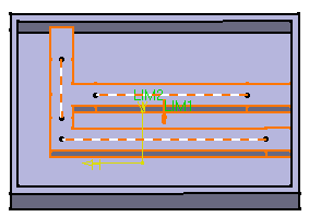
How Extrusions are Trimmed
In the following example, the network goes beyond the edges of the part.
