In this section, you will also find the following reference information:
-
Select Sketch.2 as the open profile to be extruded.
An open profile (not even closed by the revolution axis) cannot be be used as the first feature in a body.
-
Click Shaft
 .
.
A message is issued warning you that the application cannot trim the feature and that you need to change the specifications.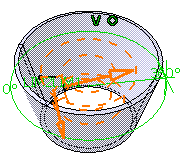
-
Click OK to close the warning message and display the Shaft Definition dialog box.
The application displays the name of the selected sketch in the Selection field from the Profile frame.
In our scenario, the profile and the axis belong to the same sketch. Consequently, you do not have to select the axis.Reverse Side
The Reverse Side button lets you choose between creating material between the axis and the profile or between the profile and existing material. You can apply this option to open or closed profiles.
-
In our scenario, as our open profile cannot be trimmed if we use the default direction, that is in the direction of the axis, click the Reverse Side button or alternatively click the arrow pointing to 360 degrees so as to obtain this preview:
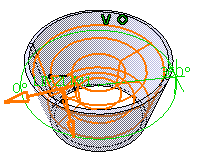
The extrusion will be done in the direction opposite to the axis and it will be trimmed to existing material.
There are three ways of reversing the revolution direction:
-
clicking the Reverse Direction button, or
-
using the Reverse direction contextual command available on the arrow or
-
just clicking the arrow.
The application previews limits, LIM1 that corresponds to the first angle value, and LIM2 that corresponds to the second angle value. The first angle value is by default 360 degrees.
-
-
Under First Limit, select the limiting type from the list and define the limiting element:
The preview of the groove in the first direction is displayed.- First Angle: Creates a feature up to the defined angle value.
- Up to next: Creates a feature up to the next intersecting feature.
- Up to last: Creates a feature up to the last intersecting feature.
- Up to plane: Creates a feature up to the defined plane.
- Up to surface: Creates a feature up to the defined surface.
-
Optional: Under Second Limit, select the limiting type from the list and define the limiting element.
Make sure that the sum of the two angles is less than 360 degrees.- Second Angle: Creates a feature up to the defined angle value.
- Up to next: Creates a feature up to the next intersecting feature.
- Up to last: Creates a feature up to the last intersecting feature.
- Up to plane: Creates a feature up to the defined plane.
- Up to surface: Creates a feature up to the defined surface.
- Optional:
In the respective Offset
boxes, enter the offset angle values for the first and second limits.

These Offset boxes are not available for the First Angle and the Second Angle limiting types.
-
Click OK to confirm.
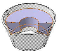
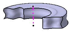
The shaft is created. The specification tree mentions it has been created.
About Profiles
- You can create shafts from sketches including several closed profiles. These profiles must not intersect and they must be on the same side of the axis.
- Moreover, you can define whether you need the whole sketch, or sub-elements only. For more information, refer to Using the Sub-elements of a Sketch.
-
You can use open profiles in geometrical sets provided you create a thin solid.
-
If needed, you can change the sketch by clicking the field and by selecting another sketch in the geometry or in the specification tree.
-
You can also use any of these creation contextual commands available from the Selection field:
-
Create Sketch: launches the Sketcher after selecting any plane, and lets you sketch the profile you need as explained in the Sketcher User's Guide.
-
Create Join: joins surfaces or curves. See Joining Surfaces or Curves.
-
Create Extract: generates separate elements from non-connex sub-elements. See Extracting Geometry.
If you create any of these elements, the application then displays the corresponding icon in front of the field. Clicking this icon enables you to edit the element.
-
-
If you have chosen to work in a hybrid design environment, the geometrical elements created on the fly via the contextual commands mentioned above are aggregated into sketch-based features.
-
But you can also edit your sketch by clicking the icon
 that opens the Sketcher. Once you have done your modifications, the
Shaft Definition dialog box reappears to let you finish your
design.
 - If you launch the Shaft command with no profile previously
defined, just click the icon
 and select a plane to access the Sketcher, then sketch the profile you
need.
 -
You can use wireframe geometry as your profile and axes created with the Axis System capability.
About Axes
-
When the selected sketch both contains a profile and an axis, the latter is selected by default as the revolution axis. This is the case in our scenario.
-
From V5R15 onwards, you can select an axis belonging to a plane distinct from the profile plane. Just make sure that the axis does not intersect the profile.
- Contextual commands creating the directions
you need are available from the Selection field:
- Create Line: see Creating Lines
- X Axis: the X axis of the current coordinate system origin (0,0,0) becomes the axis.
- Y Axis: the Y axis of the current coordinate system origin (0,0,0) becomes the axis.
- Z Axis: the Z axis of the current coordinate system origin (0,0,0) becomes the axis.
If you create any of these elements, the application then displays the corresponding icon in front of the Selection. Clicking this icon enables you to edit the element.
Thin Solids
You can add thickness to both sides of the profile used to create the shaft.
In the example below, the shaft is created using the Thick Profile option. Checking this option opens the whole Shaft Definition dialog box, which lets you then define Thickness 1 and Thickness 2. To perform the scenario, use Sketch.6.
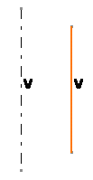
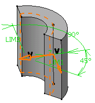
The profile is previewed in dotted line. Thickness has been added to both sides of the profile.
Neutral Fiber Option
The Neutral Fiber option adds material equally to both sides of the profile. The thickness defined for Thickness 1 is evenly distributed to each side of the profile.
Merge Ends Option
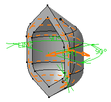
The Merge Ends option attaches the profile endpoints to adjacent geometry (axis or if possible to existing material) as illustrated below:
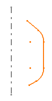
Initial profile
Resulting shaft
The profile has been attached to the axis.
Restrictions
- Using the Thick Profile option, you can create shafts from open profiles but you cannot use the Merge Ends option.
- The Thin Shaft capability does not allow you to extrude networks.
- You can select axes from the geometry area, not from the specification tree.
![]()