- Helix radius would be equal to 5mm, by default
- Helix Ramping Angle by default would be 5 deg.
- Helix Height: This would be calculated by the operation based on the hole depth and the number of levels as specified.
- Helix axis: This would be same as the tool axis. The helix will be at the centre of the hole. Arc radius of the arc joining the final circular motion: This values is not editable and would be same as the radius of the Helix specified.
Tool path for the newly added Helix macro motions: When you select standard Machining mode in circular milling operation, the approach macro and Return between level approach macro would have an additional predefined motion. You can select this from Mode drop-down menu (Creating a Circular Milling Operation) and change the parameters of helix.
Tool Path for different Combinations of selected Helix Parameter
The following sections shows the tool path for different combinations of selected helix parameter.
Note: All these motions are applicable only for Standard machining mode and Predefined-Helix mode.
Scenario 1
Number of pass = 1
Number of levels = 1
When the number pass and number of level both are 1, then the motion of the tool path would be as shown below:
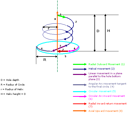
When the number of pass is 1 and the number of levels is 1, then the motion of the tool path would consist of 8 sub -motions. The helix and the final circular motion would be concentric. There would be a straight line parallel to the hole bottom plane after the helix (See number 3 in above image) and a circular arc (See number 4 in above image) that would join the helix to the final finishing circle.
Scenario 2
Number of Pass = 2 or greater
Number of levels = 1
In this scenario the tool path would be as shown below. The number of passes (or multiple pass) would be applicable only to the finishing circular motion. The helix approach would be performed only once and the circular motion would be performed according to the number of paths.
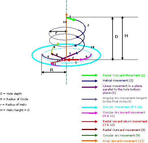
The multiple pass would work in the same way as it was working earlier. The number of passes would be applicable only to the circular motion. In short, when the number of passes is more than 1, then there would be a return in al level approach macro ( line + arc) joining the new circular tool path. This is shown by 8 and 9 in the above image. The return again would be standard retract (arc + line) as shown with 11 and 12 in the above image. For the last level it would be retract. Else for intermediate levels, it would be return in a level retract.
Circular motion is the only machining motion; multiple pass would be applied to circular motion only. Helical motion being a part of the approach and return between level approach motion, it will not participate in multiple pass.
Scenario 3
Number of pass = 1
Number of levels = 2 or greater
You can provide the number of levels from the stepover tab in the geometry dialog box. Based on inputs, the number of levels will be used to calculate the tool path. When the number of levels is more than 1, then the tool path of scenario 1 above would be repeated for the number of levels as specified.
The same is shown in the image below with number of levels as 2. The hole depth will be divided into two equal halves in this case. Similarly, the hole depth for each level would be altered based on the number of levels. Like for example, if the number of levels selected is 4, then the hole depth would be split into four equal length totalling to the total hole depth and the tool path would be computed for those many levels.
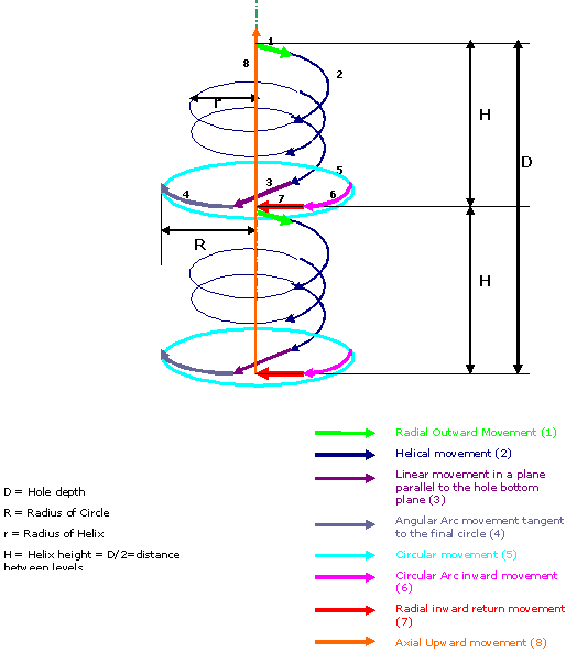
As can be seen from above image, motion 6 and 7 are the return between level retract motions. After this motion is done, the return between level approach motions would be performed. If you selected a predefined-Helix mode for return between level approach too, then after motion 7, the same motions from 1 to 7 would be performed at a lower level.
For the last level, the axial upward motion (8 in above image) would be performed.
Scenario 4
Number of passes = 2 or more
Number of levels = 2 or more
In this scenario, the motions of scenario 2 would be repeated as many times as the number of levels input given by the user. For the first level onwards (except the last level) the retract would be replaced by return between level retract and second level onwards, approach would be replaced by return between level approach. The image below shows the tool path motions for number of passes as 2 and number of levels as 2.
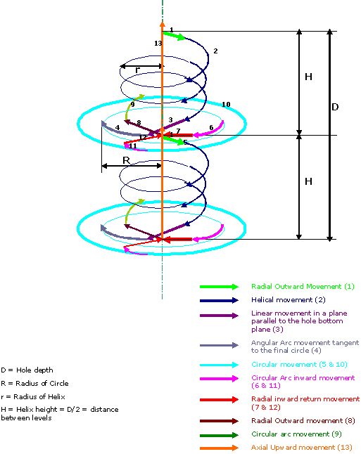
To summarize the entire tool path motion, the multiple pass would be applied to the circular motion only and the helix motion would be performed only once when the number of levels is 1. Based on the number of levels, the helix motion would be repeated with intermediate circular motion before starting the next helical movement.
Helix Radius Constraint
If radius of the helix is same as that of the final circle, then the helix motion of the tool is followed by circular motion.
The image below shows number of pass and number of levels as 1.
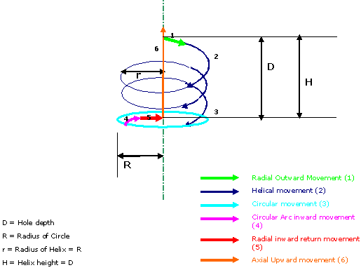
Similar logic would work for multiple pass and when number of levels is more than 1.
If the helix radius given is more than the final circle radius for that
particular part, then there would be an warning message thrown and the
radius of helix would be set to the maximum possible (i.e. hole radius)
by the operation. The warning message would be like this:
The radius of Helical motion(s) in the macros used is greater than the
smallest radius of the computed tool path. To avoid collisions, the
macro radius has been set equal to the smallest tool path radius.
Helix Radius Value
You have two options while providing the Helix radius value. You can either provide the Absolute Helix radius value or a value that will be relative to the final circular motion by selecting the particular check-box. Refer Creating a Circular Milling Operation.
If you select Absolute Helix Radius then the helix radius value will be the same as that provided on the radius manipulator.
If you select Radius difference vs next path then the helix radius will be internally computed and a difference with the next path radius will be given to the helix radius.
For example, suppose you have the path radius (radius of the circular motion) as 5mm. Now, when you give helix radius as 3mm and select Absolute Helix Radius, then the radius of the helix motion would be 3mm. Thus, the actual radius provided by you will be the helix radius as you have selected the Absolute Helix Radius radio button.
If, for the same values as mentioned above, you select the Radius difference vs next path radio button, then the helix radius will be calculated and it would be the difference between the radius of the circular motion and the radius value provided by you in the macro tool box. So in this case, the helix radius will be 5mm - 3mm = 2mm.
For the Radius difference vs next path option, the radius value provided by you will be subtracted from the radius of the circular motion and the result would be the radius of the Helix motion.