The information in this section will help you create and edit 2.5 axis Profile Contouring operations in your manufacturing program.
Select Profile Contouring
![]() then select the geometry to be machined
then select the geometry to be machined
![]() .
.
A number of strategy parameters
![]() are available for defining:
are available for defining:
- machining criteria (including a 3-axis to 5-axis converter)
Specify the tool to be used
![]() ,
NC macros
,
NC macros
![]() ,
and feeds and speeds
,
and feeds and speeds
![]() as needed.
as needed.
Profile Contouring Strategy Parameters
Profile Contouring Machining Parameters
|
Tool path style Indicates the cutting mode of the operation:
Note: A helical interpolation instruction
can be generated in the output file (APT source or Clfile) for a helix tool
path. The machine specified on the Part Operation must support Helical interpolation
and the corresponding check box must be selected in the
Machine Editor. |
|
|
Direction of cut Specifies how machining is to be done. |
|
| In
Climb milling, the front of the advancing tool (in the machining
direction) cuts into the material first.
|
|
| In Conventional , the rear of the advancing tool (in the machining direction) cuts into the material first. |
|
|
Machining tolerance Specifies the maximum allowed distance between the theoretical and computed tool path. |
|
|
Fixture accuracy Specifies a tolerance applied to the fixture thickness. If the distance between the tool and fixture is less than fixture thickness minus fixture accuracy, the position is eliminated from the trajectory. If the distance is greater, the position is not eliminated. |
|
|
Type of contour Indicates whether the contouring type of corners is: |
|
| Circular: the tool pivots around the corner point, following a contour whose radius is equal to the tool radius |
|
| Angular: the tool does not remain in contact with the corner point, following a contour comprised of two line segments |
|
| Optimized: the tool follows a contour derived from the corner that is continuous in tangent |
|
|
Forced circular: This option may be used in certain complex cases
when the Circular option does not give satisfactory results. It creates tool paths comprising of portions of circular arcs (for example, when grooves are present along the trajectory and the tool is too big to penetrate). |
|
|
Close tool path Specifies whether or not the program must close the tool path.
|
|
|
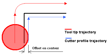
Tool position ON guide Specifies the position of the tool tip on the guiding elements. Offset on contour and driving mode are already taken into account. |
|
|
Percentage overlap Specifies the amount that the tool must go beyond the end point of a closed tool path according to a percentage of the tool diameter. |
|
|
Compensation output Allows you to manage the generation of cutter compensation (CUTCOM) instructions in the NC data output in Between Two Planes machining mode. The following options are proposed:
Any user-defined PP words in macros are added to the cutter compensation instructions generated in the NC data output. Therefore, you should be careful when specifying CUTCOM instructions in macros. A negative Offset on contour (parameter in Geometry tab page) is possible for 2D radial profile output.
|
|
|
Compensation Specifies the tool corrector identifier to be used in the operation. The corrector type (P1, P2, P3, for example), corrector identifier, and corrector number are defined on the tool. When the NC data source is generated, the corrector number can be generated using specific parameters. |
|
|
Compensation application mode Specifies how the corrector type specified on the tool (P1, P2, P3, for example) is used to define the position of the tool: Output point or Guiding point. Movement
Reverse pass (radial %) Contouring Pass Contouring Ratio |
|
|
3/5-Axis Converter When check box is selected:
For more information, see 3/5-Axis Converter. Notes
|
|
Profile Contouring Stepover Parameters
|
Sequencing Specifies the order in which machining is to be done. |
|
| Axial: axial machining is done first then radial |
|
| Radial: radial machining is done first then axial |
|
|
Side Step First On selecting this check-box, each disconnected guide is handled for all the passes (radial, axial, and finishing) and then the tool moves to the next guide and finish all the passes for that guide. For a given contour, the sequence of passes is defined by the Sequencing option. By default, this option is not selected for newly created operations. |
|
|
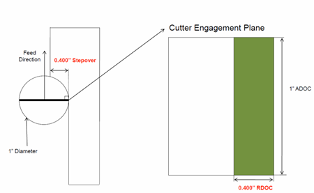
Mode For Concentric tool path, specifies the maximum tool radial engagement value. The following modes are available:
|
|
|
Percentage of tool diameter For Concentric tool path, specifies the tool diameter in percentage. This value corresponds to the maximum tool radial engagement. |
|
|
Distance between paths Defines the maximum distance between two consecutive tool paths in a radial strategy. For Concentric tool path, corresponds to the maximum tool radial engagement. The distance between passes is not fixed and varies according to the radius of curvature of the trajectory. |
|
|
Number of paths Defines the number of tool paths in a radial strategy. |
|
|
Overhang for rework areas Allows a shift in the tool position with respect to the soft boundary of the rework area. |
|
|
Axial strategy mode Defines how the distance between two consecutive levels is to be computed:
|
|
|
Maximum depth of cut Defines the maximum depth of cut in an axial strategy. |
|
|
Number of levels Defines the number of levels to be machined in an axial strategy. |
|
|
Automatic draft angle Specifies the draft angle to be applied on the flanks between the top and bottom elements. |
|
|
Breakthrough Specifies the distance in the tool axis direction that the tool must go completely through the part. Breakthrough is applied on the bottom element, which must be specified as soft. Only available in Between two planes mode. |
|
|
Smoothing
tool path along Tool Axis (%) Specifies the value to smooth the tool path when the tool path is going rapidly from a direction into a Z direction, without transition. If you specify the value as N%, the existing tool path points, within an area of size N% of tool diameter centered on the tool path discontinuity, are moved along the tool axis to smooth the tool path. |
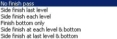
Profile Contouring Finishing Parameters
Profile Contouring High Speed Milling (HSM) Parameters
In a Profile Contouring, cornering for HSM is available for Roughing and Finishing passes in the following guiding modes:
- Between two planes
- Between curve and surfaces
- Between two curves.
Cornering applies to inside corners for machining or finishing passes. It does not apply to:
- outside corners (for example, produced by angular or optimized contouring mode).
- macros or default linking and return motions.
Profile Contouring Geometry
A Profile Contouring operation can be created in one of the following Machining modes.
Between Two Planes
Tool follows contour between top and bottom planes while respecting user-defined geometry limitations and machining strategy parameters.
You can specify the following Geometry:
- Bottom (planar face or surface) with possible Offset on Bottom. Bottom may be Hard or Soft.
- Guide contour (edges or sketch) with possible Offset on Contour.
- Top plane with possible Offset on Top. Top may be Hard or Soft.
- Start and Stop Relimiting elements with possible Offsets.
- Fixture or check elements with possible Offset on Check.
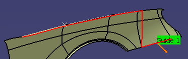
Between Two Curves (P2 functionality)
Tool follows a trajectory defined by the Guide contour and Auxiliary Guide contour while respecting user-defined geometry limitations and machining strategy parameters.
You can specify the following Geometry:
- Guide contour and Auxiliary Guide contour (edges or sketch) with possible
offsets:
- a global radial Offset on Contour
- an Axial Offset 1 the Guide contour
- an Axial Offset 2 the Auxiliary Guide contour.
- Start and Stop Relimiting elements with possible Offsets.
- Fixture or check elements with possible Offset on Check.
Guide contour is used for positioning the flank of the tool (radial positioning).
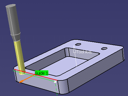
Auxiliary Guide contour is used for positioning the tool tip along the tool axis (axial positioning).
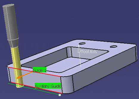
Cases when only the Guide contour is specified:
- If no Auxiliary Guide contour is specified, the Guide contour is used for positioning both the flank and the tip of the tool.
- If no Auxiliary Guide contour is specified, but an Auxiliary Guide contour offset (Axial Offset 2) is specified and it is different from the Guide contour offset (Axial Offset 1), the machining domain is defined between Guide contour Axial Offset 1 and Axial Offset 2 applied to the selected Guide contour.
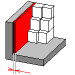
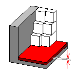
- Only one contour geometry selection is necessary to define a multi-level
tool path.
This is useful when the Guide contour is selected and there is no suitable auxiliary guide curve on the geometry to machine. In this case, just specify the Number of levels in Stepover tab.
See example below.
You can restrict machining to a specific zone by specifying Minimum depth and Maximum depth values. The depths are taken from the Guide contour. The Depth limitation check box must be activated in this case.
Side to Machine Control
You can specify the material side by selecting one or several points (vertices or Part Design points) in the authoring window. The contextual menu for material side point is:
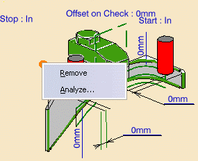
- Remove: Remove all the selected points mentioned for material side.
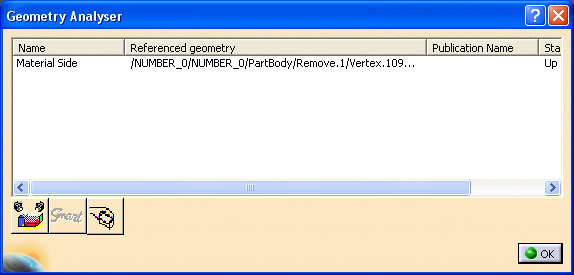
- Analyze: Geometry Analyser dialog box appears containing the selected material side points
The side to machine for the Profile Contouring machining operation
depends on a number of factors like the tool axis, the tangent of the selected
curve, the sequence of curve selection, etc.
Any change in the side to machine parameter requires a tool path re-computation
to experience the effect of this parameter.
The side to machine is on the opposite side of the material side as compared to
the guiding curve when looking along the tool axis direction.
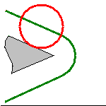
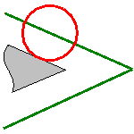
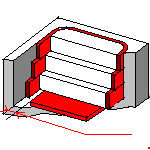
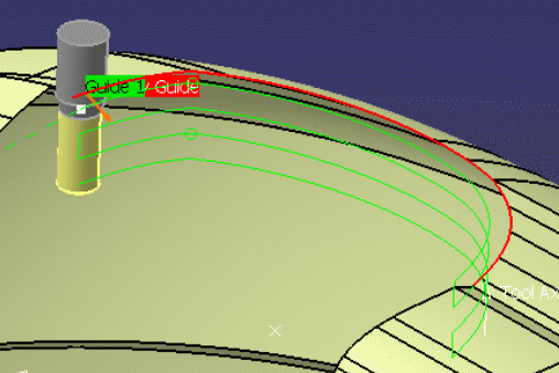
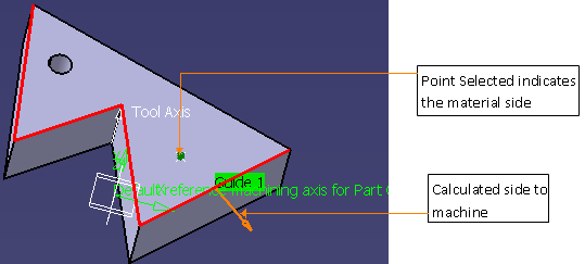
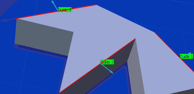
In the example below, you have selected the guide and the point indicating the
material side. Based on this additional input, the side to machine can be
calculated as shown below. The point is projected in the plane perpendicular to
the tool axis, the side to machine is the opposite of the side of the point
compared to the guiding curve.
Selecting more than one point to indicate the material side is helpful in the
case of disconnected contours or guides (that is, more than one guide is present
in the operation).
If the projected point lies on the contour, it does not allow the system to
determine the side to machine. You have to ignore this point. Only one point
(the closest one) can be associated to a contour.
A point can be associated to more than one contour. If more points than the
number of disconnected contours are selected, the additional points are ignored.
These ignored points can be seen in the Geometry Analyser dialog box.
If the side to machine proposed is not the one you require, click the orange
arrow to select the other side. We recommend that you select the points first
and then the guiding contours.
In the rare cases where the projections of the points you have selected are
equidistant to the guide curves, the system cannot decide which point belongs to
which guide curve and requires you to pick more points to define the material
side.
Between a Curve and Surfaces (P2 functionality)
Tool follows trajectory defined by a top guide curve and bottom surfaces while respecting user-defined geometry limitations and machining strategy parameters.
You can specify the following Geometry:
- Bottom (planar face or surface) with possible Offset on Bottom.
If a negative offset value is specified, it must be less than the tool corner radius value.
- Guide contour (edges or sketch) with possible radial Offset on Contour
and Axial Offset.
An Axial Offset is only taken into account when more than one axial level is defined.
- Start and Stop Relimiting elements with possible Offsets.
- Fixture or check elements with possible Offset on Check.
You can restrict machining to a specific zone by specifying Minimum depth and Maximum depth values. The depths are taken from the top guiding contour. The Depth limitation check box must be selected in this case.
By Flank Contouring (P2 functionality)
Tool flank machines vertical part surface while respecting user-defined geometry limitations and machining strategy parameters.
You can specify the following Geometry:
- Guiding flank (face parallel to tool axis) with possible Offset on Contour.
- Possible Offset on Bottom.
- Start and Stop Relimiting elements with possible Offsets.
- Fixture or check elements with possible Offset on Check.
Specifying Guiding Contours
Guiding contours can be specified in several ways:
- if the Contour Detection contextual command is set in Between Two Planes mode, select the bottom element. The boundary of the selected face will be proposed as guiding contour.
- select edges. In this case the Edge Selection toolbar appears to help you specify the guiding contour.
- select the By Belt of Faces or By Boundary of Faces contextual command. In this case the Face Selection toolbar appears to help you specify the guiding contour.
- select the Sectioning contextual command. Please refer to
Sectioning for details of how to use this capability.
Please note that the sectioning selection method is not associative.
Specifying Relimiting Elements
The guiding contour can be restricted by means of Start and Stop relimiting elements. The tool can be positioned In, On or Out with respect to a relimiting element. You can select a point or a curve as relimiting element.
You can use points created "on the fly" but be aware of the following recommendation. By deciding to use explicitly "on the fly" created points as limit, you discard any associativity with the part. Such points are only known via their XYZ coordinates. Since they are not part of the same Product as the part, we cannot ensure that their location is kept for each and any transformation applied to the part.
Basic scenario where points are created on the fly on part1, then part1 is mounted on the machine once is supported. But Advanced scenario with several transformations (e.g. create the points on the fly on part1, mount part1, change part1 to part2, mount part2) are not supported. The usage of "on the fly" created points should be limited to machining scenario where there is no move, nor change of the part.
If you expect the limiting points to always follow the part location, the creation of CATPoint in the same product as the part is the correct methodology.
If you do not look for part associativity, a fast way to specify relimiting points is to right-click the guiding contour area in the sensitive icon of the dialog box and set the Relimitation point detection contextual command. When you select a guiding contour, its extremities will be used as relimiting elements.
Note that a relimiting point can be created anywhere along the guiding contour by means of the Add relimiting point contextual command. Just right-click the relimiting element area in the sensitive icon of the dialog box and select any position along the guiding contour.
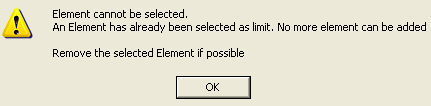
More than one relimiting elements are not supported and if you select one
relimiting element after another then the following warning message appears.
Relimiting point selection can be made easier depending on the selected screen view. For example, you can select the Normal View icon in the View toolbar and a suitable face. The screen view is then perpendicular to the selected face and it is then easier to define relimiting point locations on the guide when moving the cursor.
Note that if only one relimiting element is defined along an open guiding contour, the area to be machined is located either between:
- Limit1 and the extremity of the guiding contour
- The extremity of the guiding contour and Limit2
When relimiting elements are defined on a closed contour, the recommendation is to select the Close tool path option in order to respect the area to machine according to the Direction of cut (Climb Milling or Conventional) and the relimiting elements.
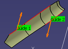
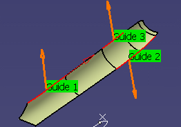
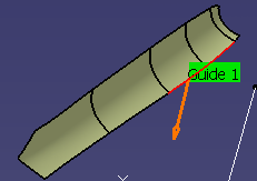
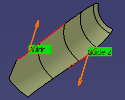
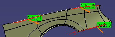
Machining Discontinuous Guiding Curves
You can machine several discontinuous groups of guiding elements in all Profile Contouring modes (except By Flank Contouring).
These contours can be selected using the Edge Selection Toolbar. A Guide.x element is displayed for each selected continuous ordered contour.
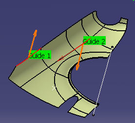
The side to mill is shown by the orange arrow. Click on the arrow to inverse the side to mill.
The order of in which the geometric elements are selected determines the order in which they will be machined.
A linking macro can be used to link two discontinuous portions of the same tool path. Otherwise, a straight line is generated.
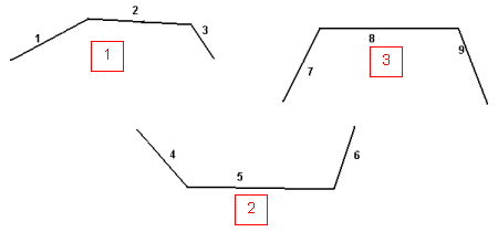
Once the selection of the guides is validated (that is, when the dialog box is displayed again), the following contextual menus become available.
On a guide in the graphic area:
On a guide in the sensitive icon of the dialog box:
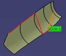
Remove Element: Removes the selected element from the Guide.
You can also remove an element by picking it again, after having launched the Edge Selection toolbar. If the guide is no longer continuous, another guide is created.
Before
 After
After
You can add elements to a guide by simply picking the element, after having launched the Edge Selection toolbar. If the element picked is connected to that guide, it is automatically added to that guide. If the element picked is connected to two guides, the element is added and the two guides are merged into one.
Remove Guide x: Removes the selected guide.
Before
After
Remove All Guides: Removes all guides
Before
After
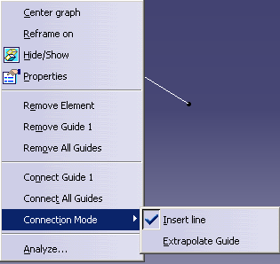
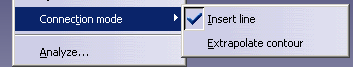
Connect Guide.x: Connects a guide to another one. Select the original guide, then the item Connect Guide.x in the contextual menu and the target guide.
Before
 After
After
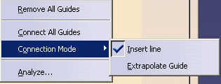
The Connection Mode allows connection either by inserting a line or extrapolating a contour.
Connect All Guides: Connects all guides into one.
Before
After
Improve Processing of Join in Profile Contouring
If you create a join with three contours, then each contiguous set of curves
is considered as a guide contour (linking motions are created before each
contour).
Checking for Collisions between Tool and Guide Elements during Macro Motions and Machining Motions
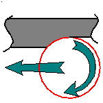
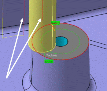
Collision checking is done during macro motions and machining motions (for corner and angle contouring). All guiding elements defined on the operation are taken into account during this verification. However, in some cases, it can be useful to deactivate collision checking with the guides (see example below).
In the following figure, collision avoidance during the circular
approach macro is not necessary.
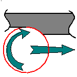
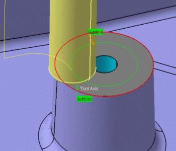
In the following figure, there is no collision avoidance during
the circular approach.
The Collision Avoidance capability allows you to manage this collision checking.
When you select Collision checking on the Geometry tab page, the following dialog box appears.
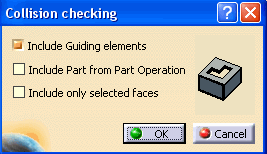
When the Include Guiding elements check box is selected, guides are checked for collisions during macro motions and machining motions. By default, the check box is selected. When the check box is not selected, no collision verification is done with the guides for macro motions and for machining motions during tool plunges.
In the specific case when there is no selected top element and no offset defined on the bottom element, there is no tool motion to avoid the guiding elements, so no collisions will be detected (for macro motions only).
When the Include Part from Part
Operation check box
is selected, the part is retrieved from the Part Operation if part is not
defined at the Machining Operation level and used in collision check for
approach/retract macro.
![]() By default, the check box is not selected.
By default, the check box is not selected.
When the Include only selected faces check box is selected,
faces are selected in the authoring window for collision checking. Face selection is activated only on selection of this check box, and the
selected faces are considered for collision checking with the macro.
The Include Part from Part
Operation and Include
only selected faces
options are mutually exclusive.
![]() By default, the check box is not selected.
By default, the check box is not selected.
Profile Contouring Tools
Recommended tools for Profile Contouring are End Mills, Face Mills, Conical Mills and T-Slotters.
Drills, Spot Drills, Center Drills, and Countersinks can also be used.
Profile Contouring Feeds and Speeds
In the Feeds and Speeds tab page, you can specify feedrates for approach, retract, machining and finishing as well as a machining spindle speed.
Feedrates and spindle speed can be defined in linear or angular units.
A Spindle output check box is available for managing output of the SPINDL instruction in the generated NC data file. If the check box is selected, the instruction is generated. Otherwise, it is not generated.
Feeds and speeds of the operation can be updated automatically according to tooling data and the Rough or Finish quality of the operation. This is described in Update of Feeds and Speeds on Machining Operation.
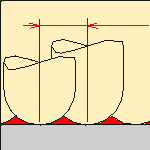
Feedrate Reduction in Corners
You can reduce feedrates in corners encountered along the tool path depending on values given in the Feeds and Speeds tab page: reduction rate, maximum radius, minimum angle, and distances before and after the corner.
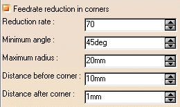
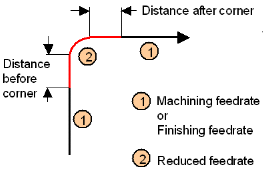
Feed reduction is applied to corners along the tool path whose radius is less than the Maximum radius value and whose arc angle is greater than the Minimum angle value. Corners can be angled or rounded.
For Profile Contouring, feedrate reduction applies to inside corners for machining or finishing passes. It does not apply for macros or default linking and return motions.
If a cornering is defined with a radius of 5mm and the Feedrate reduction in corners set to a lower radius value, the feedrate will not be reduced.
Profile Contouring NC Macros
You can define transition paths in your machining operations by means of NC Macros. These transition paths are useful for providing approach, retract and linking motion in the tool path.
An Approach macro is used to approach the operation start point.
A Retract macro is used to retract from the operation end point.
A Linking macro may be used in several cases, for example:
- to link two non consecutive paths
- to access finish and spring passes.
A Return on Same Level macro is used in a multi-path operation to link two consecutive paths in a given level.
A Return between Levels macro is used in a multi-level machining operation to go to the next level.
A Return to Finish Pass macro is used in a machining operation to go to the finish pass.
A Clearance macro can be used in a machining operation to avoid a fixture, for example.
Note: When a collision is detected between the tool and the part or a check element, a clearance macro is applied automatically. If applying a clearance macro would also result in a collision, then a linking macro is applied. In this case, the top plane defined in the operation is used in the linking macro. The top plane element must be selected in order to apply an automatic linking macro without collision.
Editing Parameters of Several Profile Contouring Operations
You can modify the parameters of several Profile Contouring operations in one shot as follows:
- Select two or more Profile Contouring operations either in the Specification tree or in the Process table.
- Right-click the highlighted operations and select Selected Objects
> Definition...
The Profile Contouring dialog box appears. - Modify any of the parameters that are available for edition.
Note: Geometry and macro definitions can be edited if all the selected operations already have identical values.
Some parameters may not be available for edition. Tool parameters cannot be edited and the Replay icon is disabled. - Click OK to apply the modified parameters of all the selected operations.
Profile Contouring P1/P2 Considerations
Note that P2 functionalities for Profile Contouring include Automatic
Draft Angle, all Finishing parameters, and Sectioning for guiding element selection.
To edit in P1 a Profile Contouring operation that was created in P2,
the following parameter values must be set:
- Automatic draft angle = 0 deg
- Finishing Mode = No finish path
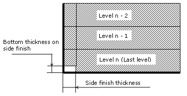
- Side finish thickness = 0.0 mm
- Side finish thickness on bottom = 0.0 mm
- Bottom finish thickness = 0.0 mm
- Spring pass = no.