In the Geometry ![]() tab:
tab:
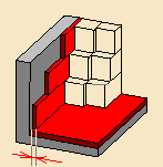
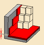
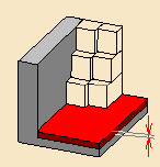
- Select the geometric components to be machined,
- Define the Limit with the Side to machine, the Stop position and the Offset
- Define the Collision Checking with the Offset on tool and the Offset on tool assembly
In the Machining
strategy tab ![]() you will find:
you will find:
- Machining Parameters:
- Stepover parameters:
- Sequencing
- Radial strategy, with Distance between paths and Number of paths
- Axial strategy, with Mode and Distance between paths
- Finishing parameters:
- Tool Axis parameters:
- HSM parameters:
- Cornering and Corner radius,
- Cornering on side finish path and Corner radius
- Compensation parameters:
Specify the
tool to be used (end mill tools ![]() or TSlotter tools
or TSlotter tools
![]() are available for this operation) and
feeds and
speeds
are available for this operation) and
feeds and
speeds
![]() .
.
You can also define transition paths in your machining operations by
means of NC macros
![]() as needed.
as needed.
Only the geometry is obligatory, all of the other requirements have a default value.
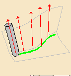
Computation of the Passes
The passes are computed as follows:
-
Computation of the ZLevel-like path:
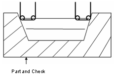
In this first step, the passes are computed following a ZLevel-like strategy with a tool axis along the view direction, taking into account the part, the check and limit lines -
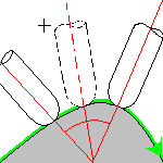
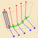
The tool rolls along the drives::
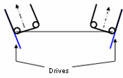
Starting from the previous position, the tool rotates around the contact point so that it becomes tangent to the drives. -
The tools comes in contact with the bottom::
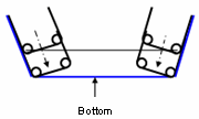
If bottom finish is required, in the last path the tool comes into contact with the bottom. -
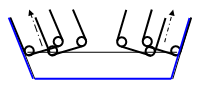
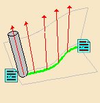
Last step: multi-path and chaining management:
Multi-Pockets Flank Contouring: Machining Parameters
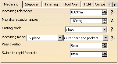
Machining tolerance
Maximum allowed distance between the theoretical and
computed tool path.
Consider the value to be the acceptable chord error.
Max discretization angle
Maximum angle between two consecutive points that the machine is able to
achieve.
- The Maximum discretization angle influences the number of points on the tool path.
- The value should be chosen carefully if you want to avoid having a high concentration of points along the tool trajectory.
- This parameter also applies to macro paths that are defined in
machining feedrate.
It does not apply to macro paths that do not have machining feedrate (RAPID, Approach, Retract, User, and so on). - Default value for Maximum discretization angle is 180
degrees.
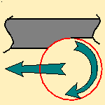
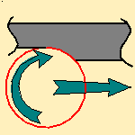
Cutting mode
Specifies the position of the tool regarding the surface to be machined. It can be:Machining mode
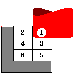
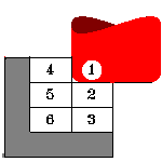
Defines the type of area to be machined:- By plane: the whole part is machined plane by plane,
- By area: the whole part is machined area by area, (not available for the Center(1) and Side(2) strategy.
then
- Pockets only: only pockets on the part are machined,
- Outer part: only the outside of the part is machined,
- Outer part and pockets: the whole part is machined outer area by outer area and then pocket by pocket.
See also Definition of Pockets and Outer part
To ensure a better surface quality, lets you define an overlap of the end of the pass over its beginning in closed tool path.
Switch to rapid feedrate
Lets you change the feedrate value in the linking passes, based on the
length of the passes.
When the length of the passes exceeds the value you have entered, the feedrate is switched to a rapid one.
Multi-Pockets Flank Contouring: Stepover Parameters
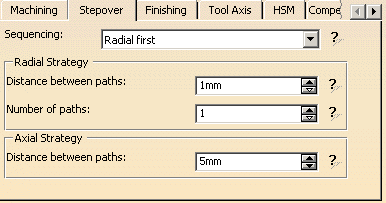
Sequencing
Specifies the order in which machining is to be done:
- Radial first: radial machining is done first then axial.
- Axial first: axial machining is done first then radial,
This option is useful when the Machining mode is set to By area.
It is not proposed when the Machining mode is set to By Plane.
The default value is Radial first.
Radial Strategy
These parameters are taken into account for semi-finishing passes in all
levels
(even for the last level in contact with the bottom if bottom finishing is
required).
If side finishing is required, one finishing pass is added by finishing
level.
Distance between paths
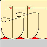
Defines the maximum distance between two consecutive tool
paths in a radial strategy. p>
Number of paths
Defines the number of tool paths in a radial strategy.
Axial Strategy
Manages the axial semi-finishing passes.
Distance between paths
Defines the maximum distance between two consecutive tool paths in an axial
strategy
Multi-Pockets Flank Contouring: Finishing Parameters
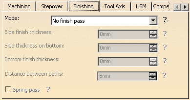
Mode
Indicates whether or
not finish passes are to be generated on the sides and bottom of the area
to machine. There are several possible combinations:
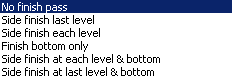
- Side finishing can be done at each level or only at the last level of the operation.
- Bottom finishing can be done without any side finishing or with different combinations of side finishing.
- If Bottom or Side finishing passes are required, the cutting mode is taken into account to manage the direction of the passes.
- Whatever the Side finish option is, only one Side finish pass per side finishing level is added (no radial management for side finishing pass).
- Side finish last level: Only one side finish is added on the last level in order to finish the Drives by only one pass.
- Side finish each level: One side finish pass per finishing level is added (managed through Axial options).
- Finish bottom only: The last passes where the tool is in contact with the bottom are detected. These passes are semi-finishing passes but the tool is in contact with the bottom. Radial parameters are taken into account as in others semi-finishing passes.
Side finish thickness
Specifies the
thickness of material that will be machined by the side finish pass.
Side thickness on bottom
Specifies the
thickness of material left on the side by the bottom finish pass.
Bottom finish thickness
Specifies the
thickness of material that will be machined by the bottom finish pass.
Distance between paths
Defines the maximum distance between two consecutive tool paths in an axial
strategy.
Spring pass
Indicates
whether or not a spring pass is to be generated on the sides
in the same condition as the previous Side finish pass. The
spring pass is used to compensate the natural `spring' of the
tool.
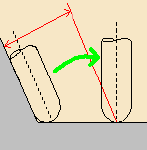
Multi-Pockets Flank Contouring: Tools Axis Parameters
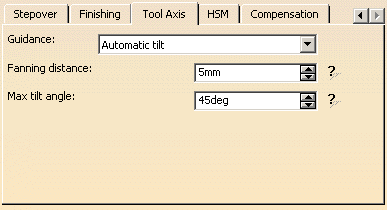
Manages the tool axis definition:
The aim is to have a tool axis tangent to the drive, with a fanning distance
to manage the transition between 2 drives, and to be collision free with the
tool shank and the tool holder. To do this, the tool is tangent to the
Drive and is contained in a plane normal to the forward direction.
Proposes two tool axis guidance strategies:
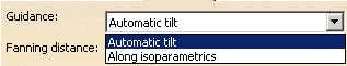
- Automatic tilt: the tool axis is tangent to the drive and is contained in a plane normal to the forward direction.
- Along isoparametrics lines: the tool axis
is tangent to the drive and follows the isoparametrics of the
drive.
This strategy does not require the Fanning distance parameter.
Fanning distance:
Distance at the beginning and at the end of the motion where the fanning
takes place.
Enter 0 to disable the fanning.
Max tilt angle:
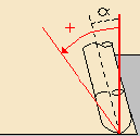
Maximum rotation angle of the tool around the contact point making the tool
tangent to the drives.
Multi-Pockets Flank Contouring: HSM Parameters
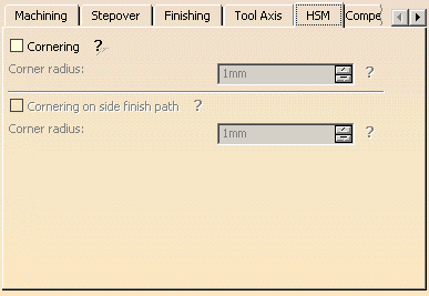
Cornering applies to inside corners for machining or finishing passes. It does not apply to:
- outside corners (for example, produced by angular or optimized contouring mode).
- macros or default linking and return motions.
Cornering
Specifies
whether or not cornering for HSM is to be done on the trajectory.
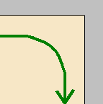
Corner radius
Specifies the radius used for rounding the corners along the
trajectory of a HSM operation. Value must be smaller than the
tool radius.
Cornering on side finish path
Specifies whether or not tool path cornering is to be done
on the side finish path.
Corner radius
Specifies the corner radius used for rounding the corners
along the side finish path of a HSM operation. Value must be
smaller than the tool radius.
Multi-Pockets Flank Contouring: Compensation Parameters
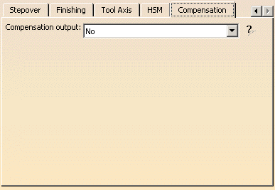
Compensation output
![]()
Allows you to manage the generation of cutter compensation
(CUTCOM) instructions in the NC data output:
- No:
- 3D Radial (PQR):
- 2D Radial - TIP (G41/G42):
Multi-Pockets Flank Contouring: Output tab
The Output tab appears once you have selected a physical machine, and selected the 2D circular interpol. check box in the machine editor.
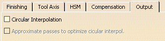
By default, the Circular Interpolation check box is not selected.
When selected, it lets you generate an arc in the roughing tool path when
the tool is in contact with a revolution surface, with its axis parallel to
the tool axis.
It also allows you to optimize the circular interpolation by approximating
passes.
Revolution surfaces can be found in cylinders, spheres, cones, torus, and complex surfaces such as chamfers, circular sweeps, etc. if those surfaces are revolution surfaces. However, note that revolution surfaces are not found in NURBS surfaces, even if those surfaces represent revolution surfaces.
The tolerance of the computed circular radius is the machining tolerance.
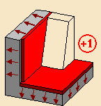
Multi-Pockets Flank Contouring: Geometry Parameters
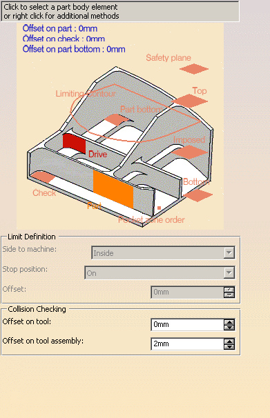
You must define:
- Part with possible offset: whole part to be machined.
- Part Bottom with possible offset: faces included in the Part that define the bottom of the pockets.
- Drive: faces that define the drive surfaces to be followed by the flank of the tool.
You can also define:
- Check element with possible offset.
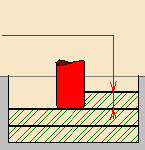
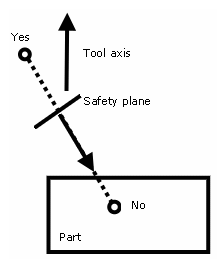
- Planes:
- Safety, i.e. the plane that the tool will rise to at the end of the
tool path in
order to avoid collisions with the part.
You can also define a new safety plane with the Offset option in the safety plane contextual menu.
The new plane will be offset from the original by the distance that you enter in the dialog box
along the normal to the safety plane.
If the safety plane normal and the tool axis have opposed directions, the direction of the safety plane normal is inverted to ensure that the safety plane is not inside the part to machine.
- Top, which defines the highest plane that will be machined on the part,
- Imposed, that the tool must obligatorily pass through.
Use this option if the part that you are going to machine has a particular shape
(a groove or a step) that you want to be sure will be cut.
If you wish to use all of the planar surfaces in a part as imposed surfaces,
select Search/View ... in the contextual menu to select them.
When searching for planar surfaces, you can choose to find either:- all of the planar surfaces in the part,
- or only the planes that can be reached by the tool you are using.
- Safety, i.e. the plane that the tool will rise to at the end of the
tool path in
- Select the planar surfaces,
- Select Offset in the contextual menu and enter a
value equal to the
machining tolerance + the offset value on part (if any):- If the machining tolerance is 0.1 mm, and there is no
offset on part,
you will enter 0.1 mm as offset for the imposed plane. - If the machining tolerance is 0.1 mm, and the offset on
part is 1 mm,
you will enter 1.1 mm as offset for the imposed plane.
- If the machining tolerance is 0.1 mm, and there is no
offset on part,
This ensures that the imposed planar surface is respected to within the offset and tolerance values.
- Bottom, which defines the lowest plane that will be machined on the part,
- Pocket zone order,
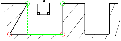
- Limiting contour: 2D limitation along the view direction.
In the example below, the view direction is shown by the arrow.
If the upper edges of the pocket are selected (green ones), only the green area of the pocket will be machined. To machine the full pocket, the limiting contour has to be the lower edges of the pocket (red ones).
Limit Definition
Defines what area of the part will be machined with respect to the
limiting contour(s).
It can either be inside or outside. In the pictures below, there are three
limiting contours on the rough stock.
The yellow areas will be machined.
Side to machine: Inside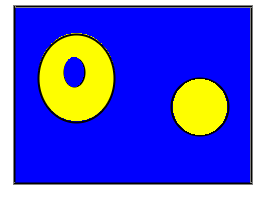 |
Side to machine: Outside |
- If you are using a limiting contour, you should define the start point so as to avoid tool-material collision.
- The use of limiting contours is totally safe is the limiting contour
is fully contained by the roughing rough stock.
Example of use: restricting the machining to a group of pockets.
Specifies where the tool stops:
- Outside stops the tool outside the rough stock.
The toolpath is computed as if the rough stock is increased by a value equal to 50% of the tool diameter in each cutting plane, - Inside stops the tool inside the rough stock.
The toolpath is computed as if the rough stock is reduced by a value equal to 50% of the tool diameter in each cutting plane, - On stops the tool on the rough stock.
This is the default (recommended) option.
Offset:
Specifies the distance that the tool will be either inside or outside the
limit line depending on the stop mode that you chose.
Collision Checking
Lets you define the Offset on tool and the Offset on tool assembly for
collision checking.
Multi-Pockets Flank Contouring: Feeds and Speeds
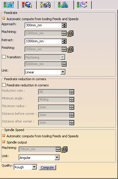
Lets you specify
feedrates for approach, retract, machining and finishing as well as a
machining spindle speed.
Feedrates and spindle speed can be defined in linear or angular units.
A Spindle output checkbox is available for managing output of the SPINDL instruction in the generated NC data file. If the checkbox is selected, the instruction is generated. Otherwise, it is not generated.
Feeds and speeds of the operation can be updated automatically according to tooling data and the Rough or Finish quality of the operation. This is described in Update of Feeds and Speeds on Machining Operation.
Feedrate Reduction in Corners
You can reduce feedrates in corners encountered along the tool path
depending on values given in the Feeds and Speeds tab page:
reduction rate,
maximum radius, minimum angle, and distances before and after the corner.
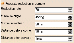
Feed reduction is applied to corners along the tool path with a radius less than the Maximum radius value and an arc angle greater than the Minimum angle value.
When machining pockets, feedrate reduction applies to inside and outside corners for machining or finishing passes. It does not apply to macros or default linking and return motions.
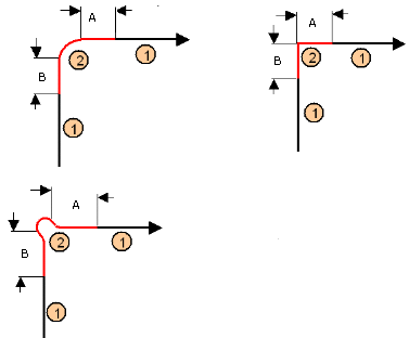
Corners can be angled or rounded, and may include extra segments for HSM
operations.
1=Machining feedrate or Finishing feedrate
2=Reduced feedrate
A=Distance after corner
B=Distance before corner
Multi-Pockets Flank Contouring: Macros Parameters
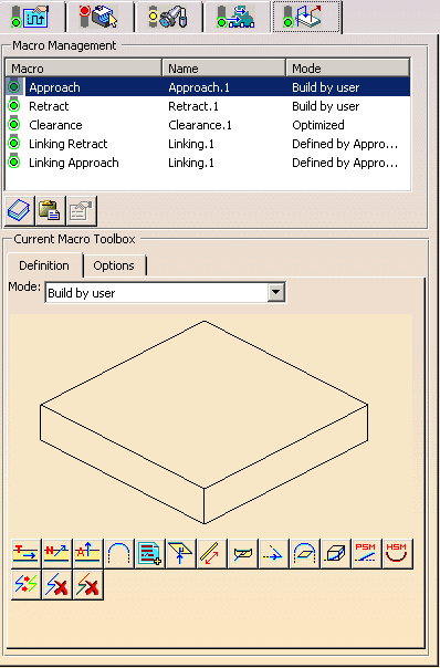
The macros managed in this operation are:
- Approach,
- Retract,
- Clearance,
- Linking Retract : for link between 2 pockets,
- Linking Approach: for link between 2 pockets.
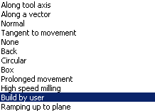
The modes available for each macro are:
For linking macros, Defined by Approach/Retract mode is also available.
For Clearance macro, the choices are:
![]()