In the ![]() tab, select the
geometric components to be machined.
tab, select the
geometric components to be machined.
In the Machining
strategy tab ![]() you will find:
you will find:
- A field dedicated to the choice of the machining strategy,
- a sensitive icon,
-
tabs dedicated to:
- the General machining strategy,
- the Center machining,
- the Side machining,
- the Output.
Specify the
tool to be used (only end mill tools
![]() are available for this operation) and
speeds and rates
are available for this operation) and
speeds and rates
![]() .
.
You can also define transition paths in your machining operations by
means of NC macros
![]() as
needed.
as
needed.
These transition paths are useful to:
- optimize retract distances,
- set the Approach and Retract parameters.
Only the geometry is obligatory, all of the other requirements have a default value.
Power Machining: Strategy parameters
Machining Strategy Type:
![]()
Two types of machining are available:
- Center(1) only, provides a roughing of the center of the part,
- Center(1) and Side(2), provides a ZLevel finishing of the sides in addition to the roughing of the centers.
The sensitive icon is adapted to the type of machining strategy selected,
and the Side tab becomes available if necessary.
For Center(1) only:
For Center(1) and Side(2):
Those drawings are for information only, 1 represents the center machining tool paths, 2 the side machining tool paths.
Tool axis:
Place the cursor on the upper vertical arrow and right-click to display the
contextual menu.
The item Select
opens a dialog box to select the tool axis:
You can choose between selection by Coordinates (X, Y, Z) or by
Angles.
Angles lets you choose the tool axis by rotation around a main axis.
Angle 1 and Angle 2 are used to define the location of the
tool axis around the main axis that you select.
- Feature-defined: you select a 3D element such as a plane that will serve to automatically define the best tool axis.
- Selection: you select a 2D element such as a line or a straight edge that will serve to define the tool axis.
- Manual: you enter the coordinates of the tool axis.
- Points in the view: click two points anywhere in the view to define the tool axis.
The Reverse Direction button lets you reverse the direction of
the axis with respect to the coordinate system origin.
When available, you can also choose to display the tool and select the
position of the tool (default or user-defined).
The item Analyze opens the Geometry Analyser.
Machining direction:
Available for the Back
and forth tool path style.
Place the cursor on the lower horizontal arrow and right-click to display
the contextual menu.
- The item
Select
opens a dialog box to select the machining direction:
- Selection: you select a 2D element such as a line or a straight edge that will serve to define the machining direction.
- Manual: you enter the coordinates of the machining direction.
- Points in the view: click two points anywhere in the view to define the machining direction.
- The item Optimize
provides an automatic selection of the machining direction:
- for each area, the main inertia axis is computed,
- then the contour defining the area is inspected to find the segment that has the smallest angle with the main inertia axis,
- this segment is used as the machining direction.
- The item Analyze opens the Geometry Analyser.
You can choose between selection by Coordinates (X, Y, Z) or by Angles.
Angles lets you choose the machining direction by rotation around a main axis.
Angle 1 and Angle 2 are used to define the location of the machining direction around the main axis that you select.
The Reverse Direction button lets you reverse the direction of the axis with respect to the coordinate system origin.
Power Machining: General Parameters
Center/Side/Bottom
definition :
Used to define the thickness to leave on the sides and on the horizontal
areas.
They are represented as follows on the icon.
Remaining thickness for sides
Be very careful when using the
Remaining thickness for sides.
Please refer to the
warning in the User Tasks Power
Machining: Side.
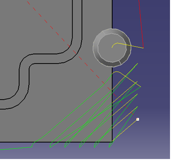
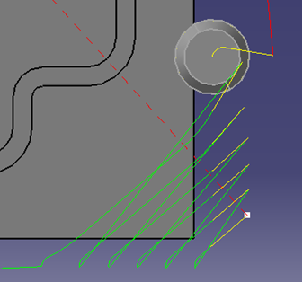
Machine horizontal areas until minimum thickness
If you select this option, a tool pass is added to machine the horizontal
areas up to the minimum thickness:
Machine horizontal areas until minimum thickness is not
active:
only the regular passes (in green) are computed according to the
axial distance.
Machine horizontal areas until minimum thickness is active:
the passes in blue are added to respect the minimum thickness (in yellow).
- When Machine horizontal areas until minimum thickness is active, the automatic horizontal areas cannot contain any side path.
- The computation of horizontal areas is not possible if the part is made of a cloud of points (STL).
- This option is not compatible with the use of offset groups.
- This option is not compatible with the option Compute with tool holder.
- Horizontal areas are always defined as pockets (no distinction outer part/pocket). You must use a limiting contour to mill Pockets only or Outer part areas.
- In circular interpolation output mode, circles cannot be created on horizontal areas. This may lead to some desynchronization with the areas above. When such a situation is detected, the horizontal area is removed to avoid overcut with the tool.
Machining tolerance
:
Maximum allowed distance between the theoretical and computed tool
path.
Consider the value to be the acceptable chord error.
Cutting mode:
Specifies the position of the tool regarding the surface to be
machined. It can be:
Examples:
- Cutting mode: Climb
Tool path style: Helical
Helical movement: Inward
The contouring tool path is in blue,
the roughing tool path is in green.
- Cutting mode: Climb
Tool path style: Helical
Helical movement: Inward
The contouring tool path is in blue,
the roughing tool path is in green.
Defines the type of area to be machined:
- By plane: the whole part is machined plane by plane,
- By area: the whole part is machined area by area, (not available for the Center(1) and Side(2) strategy.
then
- Pockets only: only pockets on the part are machined,
- Outer part: only the outside of the part is machined,
- Outer part and pockets: the whole part is machined outer area by outer area and then pocket by pocket.
See also Definition of Pockets and Outer part
Power Machining: Center Parameters
Those parameters are dedicated to the roughing of the centers of the part.
Power Machining: Center Machining Parameters
Depending on the tool path style:
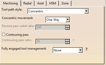
Indicates the cutting style of the operation:
- Concentric: Builds a
safe-cutting trajectory by controlling the engagement of the tool.
The trajectory created by the Concentric strategy adapts itself dynamically to ensure a safe cutting at nominal speed.
The engagement of the tool is controlled to never exceed a maximum value, even in corner areas.
This strategy is particularly recommended for hard-material milling.
In this type of material(e.g. titanium, stainless steel, ceramic, ...) the tool needs to be protected.
This has also been enhanced to reduce the computation time to make it acceptable for these cases.
Other tool path styles -based on a constant distance between passes- are not appropriate because the tool load increases significantly when milling the inside of a radius.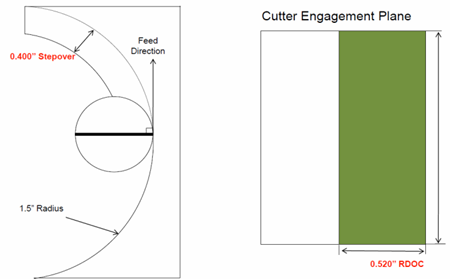
whereas the engagement is equal to the step over when milling in a straight line.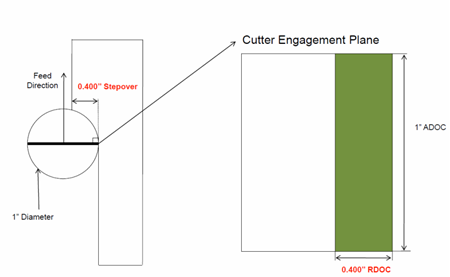
The Concentric strategy controls the tool load by modifying the distance between passes for each motion.
As a result, the tool lifetime is increased and the machining time is optimized. - Helical:
the tool moves in successive concentric passes from the boundary of the area to machine towards the interior.
The tool moves from one pass to the next by stepping over.
The associated parameters are Machining tolerance, Cutting mode, Machining mode, Helical movement, Always stay on bottom
and Forced cutting mode on part contour. - Back and forth: this cutting style is made of two kinds of
passes:
- back and forth passes,
- part contouring passes. The contouring passes can be applied before or after the back and forth passes.
The associated parameters are Machining tolerance, Cutting mode, Machining mode, Contouring pass and Contouring pass ratio.
You can choose to apply the High speed milling option to this tool path style.
You can also define the machining direction.
Movement
- When Movement is set to One-Way, the tool path uses the selected cutting direction.
- When Movement is set to Zig-Zag, the tool path
is optimized using both cutting directions (Climb and
Conventional).
The selected cutting mode is the main direction. Modifying it could change the trajectory.
Reverse pass (radial %)
Lets your define the
reverse radial engagement when milling in the reverse direction, that is in
the direction that is not selected as the Direction of cut.
The value is
a percentage of the main radial engagement.
A value equal to 100% keeps
the same engagement for the main and the reverse direction.
Contouring pass
For Power Machining using a Back and Forth or Concentric
tool path style, lets you decide whether the contouring passes are applied prior to or after
the back and forth passes.
If the contouring passes are applied prior to the back and forth passes,
the contouring passes can be computed on intermediate Z levels
in order to reduce the tool loading.
A: Distance between 2 part contouring passes
B: Distance between 2 back and forth passes
In that case:
- an approach motion is done on each motion,
- the back and forth passes are organized to avoid full diameter milling,
- you can define the Number of contours.
Contouring pass ratio
For Power Machining using a Back and Forth or Concentric
tool path style, adjusts the position of the final pass for removing scallops.
This is done by entering a percentage of the tool diameter (0 to 50).
Helical movement:
Specifies the way the tool moves in a pocket or an external zone. It can be:
- Inward: the tool starts from a point inside the zone and
follows inward paths parallel to the boundary.

- Outward: the tool starts from a point inside the zone and
follows outward paths parallel to the boundary.
- Both:

- for pockets, the tool starts from a point inside the pocket and follows outward paths parallel to the boundary.
- for external zones, the tool starts from a point on the rough stock boundary and follows inward
paths parallel to the boundary.
in particular in the computation of the ramping approaches.
This improvement may cause a computation failure, resulting in this specific message:
The tool core diameter is not compatible with some ramping motions.
This option becomes available when at least one tool path style is set to Helical.
When machining a multi-domain pocket using a helical tool path style, this parameter forces the tool to remain in contact with the pocket bottom when moving from one domain to another. This avoids unnecessary linking transitions.
Always stay on bottom is not active:
Always stay on bottom is active:
Forced
cutting mode on part contour
Only used with the helical tool path style.
With part contouring switched on, the tool goes round the outside contour of
the part before continuing.
Deactivating this option allows you to gain machining time.
The tool that you are using and the part you are working on must be such
that contouring the rough stock is superfluous.
With part contouring switched on. Note how the tool went round the area to
machine first:
With part contouring switched off. Note that the tool goes straight
into helical mode:
- each area is machined,
- then there is a contouring pass around each areas,
- followed by a contouring pass around the whole part when the remaining material is less than the tool radius,
- approach and retract motions are computed for all those tool paths.
Starting with R17, all the tool paths around the part are chained, thus reducing the number of air cuts as there are fewer approach and retract motions.
This parameter is available when:
- the
Machining mode is
set to:
- Pockets only
- Outer part and pockets
- the
Tool path style is set to:
- Helical
- Concentric
It is used to manage full material cut in hard material roughing, where the stepover is not always respected and where the tool can be damaged. This can be avoided by switching to a trochoid motion that reduces the stepover, or by adding machining planes to reduce the load on the tool.
Full engagement is detected when:
- more that 75% of the tool diameter is engaged in the material,
- or more than 120 degrees of the tool is in contact with the material.
It can be set to:
- None: no management of the tool engagement.
- Trochoid: adds a trochoid motion in areas where the
stepover is not respected. The trochoid motion is managed by the
Minimum trochoid radius.
- the arrows show where full material milling is detected
- the arrows show where full material milling is replaced by
trochoidal motions
- the arrows show where full material milling is detected
- MultiPass: adds machining planes in areas where the
stepover is not respected. The distance between those additional planes
is managed by the parameter Maximum full material cut depth.

In previews and replays, a warning is displayed if Maximum full material cut depth is greater than the Maximum cut depth.
Power Machining: Center Radial Parameters
Stepover
It can be defined by:
- the Overlap ratio, i.e. the overlap between two passes,
given as a percentage of the tool diameter
(Tool diameter ratio),
- the Overlap length
between two passes,
- the Stepover ratio, i.e. the stepover between two passes,
given as a percentage of the tool diameter
(Tool diameter ratio),
- the Stepover length between two passes given by the
Max. distance between pass,
Overhang: Available in all tool path styles.
As this option is activated by default in all new processes, it is not
visible in the dialog box.
However, if you are editing an older process,
you can see the option in the dialog box and decide to activate it or nor.
By
shifting the tool position with respect to the soft boundary of the
machining domain, Overhang defines the correct radial engagement of the tool. The
possible options are:
- None: The tool position is
not shifted: The tool is positioned on the middle of the boundary. This
is the position by default.
- Same as stepover: The tool
position is shifted by the stepover value, up to 50% of the tool
diameter (greater values are not supported).
Power Machining: Center Axial Parameters
Maximum cut depth:
Depth of the cut effected by the tool at each pass
Variable cut depths
When the dialog box opens the distance between passes from the top to
the bottom of the part is constant and is the same as the Maximum cut
depth.
Change the Distance from top value and the
Inter-pass value and
then press Add to give a different depth value over a given
distance.
In the example below the cut depth:
- from the top of the part to 15mm from the top is of 2 mm,
- from 15mm from the top to 25mm from the top is 5mm,
- and from 25 mm from the top to the bottom of the part is 10 mm.
Power Machining: Center High Speed Milling Parameters
High speed milling:
Activates and defines the parameters for High speed milling.
Corner radius:
Defines the radius of the rounded ends of passes when cutting with a
Concentric tool path style and the radius of the rounded end of retracts
with Helical and Concentric tool path styles.
The ends are rounded to give a smoother path that is machined much faster.
This is what a tool path will look like if you do not use high speed milling
parameters:
Here is the same tool path with the High speed milling switched on. Note how
the round tool path ends.
In both cases a concentric tool path style is used.
Similarly, here is what retracts look like without the high speed milling
option:
And here is the same tool path with high speed milling switched on:
- With HSM and helical mode, the corner radius must be less than half
the stepover distance.
It will be forced to this value. - The corner radius is not applied to the finish path.
When available and active, defines the corner radius of all the tool paths in contact with the part.
This radius must be smaller than the value set for the Corner radius parameter
Power Machining: Center Zone Parameters
Pocket filter:
Check this option to activate the filter for small passes.
The non-cutting diameter of the tool can be entered in the Tool tab, pushing
the More button.
It is given as an information only in the Zone tab.
Not all pockets will be machined if there is not enough depth for the tool
to plunge.
A null value means that tool is allowed to plunge in pockets. The size of
the smallest pocket is given below the data field.
The Tool core diameter is taken into account:
- in pockets (default operating mode),
- also for outer parts when limiting contours are used.
When areas are filtered (i.e. not machined) with the Tool core diameter, the areas beneath those areas are not machined.
Power Machining: Side Parameters
Those parameters are dedicated to the finishing of the sides of the
parts.
This is done by inserting Zlevel passes after each center level is machined.
Whenever possible, the tool path must be made of arc of circles.
For each side ZLevel pass, an automatic Approach and Retract are computed
and have the following features:
- the approach point is situated on the longest linear segment of the area,
- an arc of circle with a particular radius (by default it is the HSM corner radius),
- a segment in order to insure that the tool plunges beside the material and that the compensation can be activated
Power Machining: Side Machining Parameters
Bottom finish
thickness:
Defines the thickness of material left on the bottom by the ZLevel side pass
so that the tool does not touch the bottom of the previous center machining
pass:
This thickness is usually very small.
Compensation output:
![]()
Defines how compensation instructions are generated in the NC data output:
- None: there is no compensation
- 2D radial tip: compensation is computed in a plane normal
to the tool axis,
and activated with respect of the cutter side (left or right).
The radius compensated is the cutter radius, the output is the tool tip point (XT, YT, ZT).
Power Machining: Side Axial Parameters
Maximum cut depth
Defines the maximum pass depth for the ZLevel passes: the Zlevel
passes are synchronized with the center passes.
Power Machining: Output tab
The Output tab appears once you have selected a physical machine, and selected the 2D circular interpol. check box in the machine editor.
By default, the Circular Interpolation check box is not selected.
When selected, it lets you generate an arc in the roughing tool path when
the tool is in contact with a revolution surface, with its axis parallel to
the tool axis.
Revolution surfaces can be found in cylinders, spheres, cones, torus, and complex surfaces such as chamfers, circular sweeps, etc. if those surfaces are revolution surfaces. However, note that revolution surfaces are not found in NURBS surfaces, even if those surfaces represent revolution surfaces.
Geometry
You can also specify the following geometry:
- Part with possible offset.
- Rough stock. If you do not have a rough stock you can
create one
automatically.
You must define a rough stock if you have not already defined one in the Part Operation.
See the Machining Infrastructure user's guide for further information. - Check element with possible offset.
The check element is often a clamp that holds the part and therefore is not an area to be machined.
-
Safety plane.
The safety plane is the plane that the tool will rise to at the end of the tool path in order to avoid
collisions with the part.
You can also define a new safety plane with the Offset option in the safety plane contextual menu.
The new plane will be offset from the original by the distance that you enter in
the dialog box along the normal to the safety plane.
If the safety plane normal and the tool axis have opposed directions,
the direction of the safety plane normal is inverted to ensure
that the safety plane is not inside the part to machine.
- Top plane which defines the highest plane that will be machined on the part,
- Bottom plane which defines the lowest plane that will be machined on the part,
- Imposed plane
that the tool must obligatorily pass through.
Use this option if the part that you are going to machine has a particular shape (a groove or a step)
that you want to be sure will be cut.
If you wish to use all of the planar surfaces in a part as imposed
surfaces,
use the Search/View ... option in the contextual menu to select
them
(the Part to machine must be selected first).
When searching for planar surfaces, you can choose to find either:
- all of the planar surfaces in the part,
- or only the planes that can be reached by the tool you are using.
- Select the planar surfaces,
- Select Offset in the contextual menu and
enter a value equal to the machining tolerance + the offset value on part (if any):- If the machining tolerance is 0.1 mm, and there is no offset on
part,
you will enter 0.1 mm as offset for the imposed plane. - If the machining tolerance is 0.1 mm, and the offset on part is 1
mm,
you will enter 1.1 mm as offset for the imposed plane.
- If the machining tolerance is 0.1 mm, and there is no offset on
part,
This ensures that the imposed planar surface is respected to within the offset and tolerance values.
- When a face is selected as a Bottom plane or an
Imposed plane, the contextual menu item
Force to machine
imposes the computation of the tool path on this face. - Using the two Imposed
icons, you can define two sets of imposed planes,
with eventually a different offset on each set.
- Start point
where the tool will start cutting.
Whatever the tool path style is, when drilling holes exist, define start points and set the Mode in the Definition tab of macros to Radial only to avoid any plunge or ramping macros. If a radial engagement is not possible (collision with part or with the residual material), the roughing tool path is stopped:
If you leave the Mode in the Definition tab of macros to Plunge, no control will be carried out when the tool will plunge at the start point.
If the start point is not correct or if no start point has been defined for a given area, no start point will be computed automatically and the tool will plunge in material.- Start points:
- manage contouring passes.
- manage outer part and pockets. Therefore, you do not need to deactivate previous drilling operations.
- taken into account if they lay inside the drilling hole even if they are not completely outside the part, check surfaces or rough stock.
- For each start point, the point to join after the start point
must lay in a circle defined by a maximum radius. This maximum
radius can be activated and edited in the contextual menu of
Start point(s):
By default, the check box Activate is not selected, no maximum radius is applied to the start points, all start points are taken into account whether they lie within the circle or not. Select the check box to take the maximum radius into account. - Select the contextual menu item Plunge on point
to make the plunge of the tool at the start point compulsory.
When this item is not selected, the tool will not plunge at the start point. The start point will only impose the direction of the radial engagement.
- Concentric tool path style:
Start points are automatically defined. In this case, the start point is the center of the largest
circle that can be described in the area to machine. Lateral approach modes cannot be used. - Helical Tool path styles:
Whenever possible, the end of the engagement associated to the start point corresponds to
the beginning of the sweeping path.
- Start points:
- Inner points (only active if the Drilling mode has been
selected in the Macro data tab).
There are specific conditions for inner points:
- they are usable for pockets only,
- They must not be positioned so as to cause collisions with either the part or the check element.
If an inner point for a given pocket causes a collision, the tool will adopt a new inner point generated automatically.- the inner point must lay inside the pocket or inside the portion of the pocket that is machined.
- If there are several inner points for a given pocket, the one that is used is the first valid one
(in the order in which they were selected) for that pocket.- A point can not be valid for several pockets.
- Limiting contour which defines the machining limit on the part, with the Side to machine parameter.
Please refer to the Selecting Geometric Components to learn how to select the geometry.
Minimum thickness to machine:
Specifies the minimum material thickness that will be removed
when using overshoot or in a rework operation.
- The red arrow points to the Minimum thickness to machine,
the green arrows point to the material that is not removed,
the black arrow points to the material removed,
the grey arrow points to the part to machine.
- In red, the Minimum thickness to machine,
in green, the material that is not removed,
in black, the material removed,
in grey, the part to machine.
Minimum thickness to machine + twice the value of the tolerance.
Therefore, on a level below you may have to mill a thickness amounting to the value of the
Minimum thickness to machine + twice the value of the tolerance of one or several levels above.
Defines what area of the part will be machined with respect to the limiting contour(s).
It can either be inside or outside. In the pictures below, there are three limiting contours on the rough stock.
The yellow areas will be machined.
Side to machine: Inside
Side to machine: Outside
- If you are using a limiting contour, you should define the start point so as to avoid tool-material collision.
- The use of limiting contours is totally safe is the limiting contour
is fully contained by the roughing rough stock.
Example of use: restricting the machining to a group of pockets. - But we strongly advise against using a limiting contour that is
partly outside the roughing or residual rough stock.
Example: roughing rework or a first roughing with a complex rough stock).
In that case, we recommend that you define a surface with holes or a mask to define the machining zone to work on.
Specifies where the tool stops:
- Outside stops the tool outside the rough stock.
The toolpath is computed as if the rough stock is increased by a value equal to 50% of the tool diameter in each cutting plane, - Inside stops the tool inside the rough stock.
The toolpath is computed as if the rough stock is reduced by a value equal to 50% of the tool diameter in each cutting plane, - On stops the tool on the rough stock.
This is the default (recommended) option.
Offset:
Specifies the distance that the tool will be either inside or outside the
limit line depending on the stop mode that you chose.
Force replay:
only used for reworking operations.
Its purpose is to compute the residual rough stock remaining from operations
preceding the current one,
providing a rough stock has not been defined for this operation. Use it
before pressing Replay.
Ignore holes on
stock:
Select this check box to ignore holes which are on the rough stock, with
Tool path style set to Helical or Zig-zag.
Once this check box is selected, define the diameter under which holes are
to be ignored.
Compute with
tool holder:
Select this check box to compute the tool path as to avoid collisions with
the tool holder.
When this check box is selected, you can define an offset on the tool holder
assembly.
When this check box is cleared, the tool path is computed only with the
tool.
Power Machining: Feeds and Speeds
In the Feeds and Speeds tab page, you can specify feedrates for approach, retract, machining and finishing as well as a machining spindle speed.
Feedrates and spindle speed can be defined in linear or angular units.
A Spindle output checkbox is available for managing output of the SPINDL instruction in the generated NC data file. If the checkbox is selected, the instruction is generated. Otherwise, it is not generated.
Feeds and speeds of the operation can be updated automatically according to tooling data and the Rough or Finish quality of the operation. This is described in Update of Feeds and Speeds on Machining Operation.
- Feedrate reduction is not available for all tool path styles.
- Feedrate management is possible for Helical, Back and forth tool path styles only.
Feedrate Reduction in Corners
You can reduce feedrates in corners encountered along the tool path
depending on values given in the Feeds and Speeds tab page:
reduction rate,
maximum radius, minimum angle, and distances before and after the corner.
Feed reduction is applied to corners along the tool path whose radius is less than the Maximum radius value and whose arc angle is greater than the Minimum angle value.
When machining pockets, feedrate reduction applies to inside and outside corners for machining or finishing passes. It does not apply for macros or default linking and return motions.
Corners can be angled or rounded, and may include extra segments for HSM
operations.
1=Machining feedrate or Finishing feedrate
2=Reduced feedrate
A=Distance after corner
B=Distance before corner
Slowdown Rate
You can use Slowdown rate in the Feeds and Speeds tab page to
reduce the current feedrate by a given percentage.
In Helical tool paths, the reduction is applied to the first channel cut.
In Back and Forth tool paths, the reduction is applied to the first channel
cut and to the transitions between passes.
Combining Slowdown Rate and Feedrate Reduction in Corners
If a corner is included in a Slowdown path, the general rule is that the lowest percentage value is taken into account.
For example, if the Slowdown rate is set to 70 % and Feedrate reduction
rate in corners is set to 50%, the feedrate sequence is:
100%, 70% (entry in slowdown), 50% (entry in corner), 70% (end of corner,
still in slowdown), 100% (end of slowdown).
If Feedrate reduction rate in corners is then set to 75%, the feedrate
sequence is:
100%, 70% (entry in slowdown), 70% (entry in corner: 75% ignored), 70% (end
of corner, still in slowdown), 100% (end of slowdown).
Power Machining: Macro data
For more information on how to save or load an existing macro, please refer to Build and use a macros catalog.
Optimize retract
This button optimizes tool retract movements.
This means that when the tool moves over a surface where there are no
obstructions,
it will not rise as high as the safety plane because there is no danger of
tool-part collisions. The result is a gain in time.
- In some cases (where areas of the part are higher than the zone you
are machining and when you are using a safety plane),
the tool will cut into the part. When this happens, deactivate the Optimize retract button. - The axial safety distance should be larger than the axial cut depth of the last Power Machining operation.
- Parameter Optimize Retract is only available for the part to machine, not for the rough stock.
Maximum distance that the tool will rise to when moving from the end of one pass to the beginning of the next.
Approach distance
Engagement distance for plunge mode.
Radial
safety distance
Distance that the tool moves horizontally before it begins its approach.
select this check box to create circular engagements from external zones:
- a cornerization arc is inserted in the approach movements.
- all the movements will be tangent except when a collision could occur between the arc and the part.
Once selected, define the radius of this circular approach.
Engage from outside:
In case of open pockets, select this check box to create engagements from
external zones.
- By default, the point used for external engagement is the point on the
rough stock closest to the pattern start point.
- In case of collision, V5 tries to compute a pattern avoiding
collision.
- If some collisions remain in planes you have defined, you can define a
start point to help find out a pattern which avoids the collision.
- If some collisions remain in some planes even with the defined start
point, a ramping approach will be created.
Specifies the engagement of the tool in the material:
- Plunge: the tool plunges vertically,
- Drilling: the tool plunges into previously drilled holes.
You can change the Drilling tool diameter, Drilling tool angle and Drilling tool length, - Ramping: the tool moves progressively down at the Ramping angle,
- Helix: the tool moves progressively down at the ramping
angle with its center along a (vertical)
circular helix of Helix diameter. - Radial only:
When drilling holes exist, define start points and use Radial only to avoid any plunge or ramping macros.
If a radial engagement is not possible (collision with part or with the residual material), the roughing tool path is stopped.
Those approach modes apply to pockets.
- If the Tool Path is Concentric, the approach is always Helix, either on outer areas or pockets.
- Ramping approach mode applies to pockets but also outer areas in given conditions:
- If a limit line is used, the tool will approach outer areas of the part and pockets in ramping mode.
- If a lateral approach is not possible (due to the check element), the approach is made in ramping mode.