Click
![]() , then select the
geometry
, then select the
geometry
![]() to be machined.
to be machined.
A number of strategy parameters
![]() are available.
are available.
Specify the tool to be
used
![]() ,
feeds and speeds
,
feeds and speeds
![]() ,
and
NC macros
,
and
NC macros
![]() as needed.
as needed.
Multi-Axis Spiral Milling: Strategy Parameters
The Multi-Axis Spiral Milling strategy parameters are distributed into 5 tabs:
In addition to the parameters available in those tabs, you have to select a tool path style, and to define the view axis, the tool axis and the start direction, depending on the tool path selected.
Tool path style
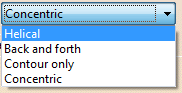
Indicates the cutting style of the operation:
- Helical:
the tool moves in successive concentric passes from the boundary of the area to machine towards the interior.
The tool moves from one pass to the next by stepping over.
Back and forth: this cutting style is made of two kinds of passes:- back and forth passes,
- part contouring passes.
- Contour only: only machines around the external contour of the part.
|
Tool Axis, View Direction, Start Direction
The tool axis is optional
and used for Fixed axis strategy.
Place the cursor on the arrow
A and right-click to display the contextual menu.
The item Select
opens a dialog box to select the tool axis:
The view direction is visualized as the V axis.
Place the cursor on the arrow
V and right-click to display the contextual menu.
The item Select
opens a dialog box to select the view direction:
The Start direction is available for the
Back
and forth tool path style.
Place the cursor on the lower horizontal arrow S
and right-click to display
the contextual menu.
The item
Select
opens a dialog box to select the start direction:
You can choose between selection by Coordinates (X, Y, Z) or
by Angles.
Angles lets you choose the machining direction by rotation around a main
axis.
Angle 1 and Angle 2 are used to define the location of
the machining direction around the main axis that you select.
Drop-down list
- Feature-defined: you select a 3D element such as a plane that will serve to automatically define the best direction or axis.
- Selection: you select a 2D element such as a line or a straight edge that will serve to define the direction or axis.
- Manual: you enter the coordinates of the direction or axis.
- Points in the view: click two points anywhere in the view to define the direction or axis.
![]() sets the direction to that of the normal to screen.
sets the direction to that of the normal to screen.
The Reverse Direction button lets you reverse the direction of the axis with respect to the coordinate system origin.
The item Analyze opens the Geometry Analyser.
Multi-Axis Spiral Milling: Machining Parameters
Machining tolerance
Maximum allowed distance between the theoretical and
computed tool path.
Consider the value to be the acceptable chord error.
Direction of cut
Specifies the position of the tool regarding the surface to be machined.
It can be:
 |
 |
| Climb | or Conventional. |
Examples:
- Direction of cut: Climb
Tool path style: Helical
Helical movement: Inward
The contouring tool path is in blue,
the roughing tool path is in green.
- Direction of cut: Climb
Tool path style: Helical
Helical movement: Inward
The contouring tool path is in blue,
the roughing tool path is in green.
Helical movement
Available when Tool path style
is set to Helical.
- Outward: the tool path will begin at the middle of the area
to machine and work outwards.
- Inward: the tool path will begin at the outer limit of the
area to machine and work inwards.
Max discretization angle
Specifies the maximum angular change of tool axis between tool positions.
It is used to add more tool positions (points and axis) if value is
exceeded.
Always stay on bottom
Available when Tool path style is set to
Helical or
Back
and forth.
When machining a multi-domain pocket using a helical tool path style,
this parameter forces the tool to remain in contact with the pocket bottom
when moving from one domain to another. This avoids unnecessary linking
transitions.
Example:
Always stay on bottom is not active:
Always stay on bottom is active:
Movement
- When Movement is set to One-Way, the tool path uses the selected cutting direction.
- When Movement is set to Zig-Zag, the tool path
is optimized using both cutting directions (Climb and
Conventional).
The selected cutting mode is the main direction. Modifying it could change the trajectory.
Reverse pass (radial %)
Lets your define the
reverse radial engagement when milling in the reverse direction, that is in
the direction that is not selected as the Direction of cut.
The value is
a percentage of the main radial engagement.
A value equal to 100% keeps
the same engagement for the main and the reverse direction.
Multi-Axis Spiral Milling: Radial Parameters
Distance between paths
Specifies the distance between two consecutive paths.
Contouring pass
For multi-axis spiral milling using a Back and Forth or
Concentric tool path style, adds a contouring pass at the end of the back and forth path.
Multi-Axis Spiral Milling: Axial Parameters
Maximum cut depth
Depth of the cut effected by the tool at each pass.
Number of levels
Defines the number of parallel passes to be computed.
Multi-Axis Spiral Milling: Tool Axis Parameters
Note that modifications of the tool axis generated by the mode you have selected apply only to the machining passes, not to the between paths passes.
You can define several axes with this icon:
- V, for the view direction,
- A, for the tool axis direction.
The view directions defines the machining guiding plane: machining is done in planes parallel to the guiding plane.
The view direction defines the accessible areas for the tool. These areas are accessible if the angle between the view direction and the normal to surface is less than 85 degrees.
The tool axis definition depends on the Tool axis mode. The tool axis
arrow turns white when its definition box is not available
(e.g. when the tool axis is defined through a point or a line, ...).
Clicking one of the direction arrows displays its definition box.
- View direction:
- Tool axis direction:
Tool axis mode
Note that modifications of the tool axis generated by the
mode you have selected apply only to the machining
passes, not to the between paths passes.
The tool axis can be fixed (see
Tool Axis above) or
normal to the part (i.e. the tool is normal to the bottom of the pocket with
an angular tolerance).
When the tool axis is normal to the part, there is a risk of collision as
shown below.
Multi-Axis Spiral Milling: HSM Parameters
Select the High Speed Milling check box to
activate this mode.
The two tabs below becomes available. One deals with the corner tool passes,
the other with the transition tool passes.
Corner radius
Specifies the radius used to round the ends of passes
to give a smoother path that is machined much faster.
Limit angle
Specifies the minimum angle the tool pass must form to allow the rounding
of the corners.
Extra segment overlap
Specifies an overlap for the extra segments that are
generated for cornering in a high speed milling operation. This ensures that
there is no leftover material in the corners of the tool path.
Transition radius
Specifies the radius at the extremities of a
transition path in a high speed milling operation.
![]()
Transition angle
Specifies the angle of the transition path that
ensures a smooth move from one path to another in a high speed milling
operation.
![]()
Transition length
Specifies the minimum length of the straight segment
of the transition path in a high speed milling operation.
![]()
Multi-Axis Spiral Milling: Geometry
You can select:
- a part to machine (mandatory) with a possible offset,
- The thickness of the offset can be negative.
- If you want to use a negative value, the tool corner radius must be greater than the absolute value of the offset.
- guide faces (optional if soft guide contours are selected,
mandatory otherwise) with possible offset. Guide
faces:
- can be used to define islands,
- are used to compute the last pass in bitangency with the selected part.
To get a regular tool path and tool axis variation, and a precise tool location on the path in bitangency, we recommend that you select all the guide faces where the tool can be in contact (i.e. the strip of vertical faces and the horizontal surfaces connex to the vertical ones) as shown below:
- a soft guide contour (mandatory if guide faces are not selected, optional otherwise). It closes the guide faces if the pocket is open.
- a local reduction of the distance between paths can be observed near the soft guide because the tool contact point (and not the tool end point) is on the soft guide.
- The Tool axis mode Normal to part is respected for Soft guide contours laying inside the Part surfaces; it may be not respected if Soft guide contours are laying on the Part surfaces boundary. In this case, the tool axis is computed with the help of the View Direction.
- a check (optional) with possible offset,
-
Start points: By default, there is no user-defined start point and
the system determines automatically the start point.
When several points are selected, the system automatically performs the mapping of each selected point with the area to be machined. In each area:- when a point selected by the user exists, the system uses this point as start point,
- when more than one point selected by the user exist, the system uses one of the user point (any of the selected ones).
- the ordering of the selected points does not matter.
- an offset group.
Geometry can also be defined using geometrical zones.
Collision Checking
Collision checking can be performed on the
shank of the tool or on the
shank of the
tool plus the tool assembly (With tool
assembly selected).
To save computation time, use tool assembly
only if the geometry to be checked can interfere
with the upper part of the cutter.
You can define an Offset on tool and an Offset on tool assembly
to avoid collisions.
Multi-Axis Spiral Milling: Tools
Recommended tools are end mill tools.
Multi-Axis Spiral Milling: Macro Parameters
General information about macros can be found in
NC Macros.
Information about the operating mode can be found in
Defining Macros.
Information about Surface Machining macro parameters can be found in
Macro Parameters.
Standard macros are available:
- approach macro to approach the operation start point,
- retract macro to retract from the operation end points,
- linking macros to link two non consecutive tool paths,
- clearance macros.
The macros available for approach, retract and linking
are:
Those for the clearance are: