-
Right-click the section view in the specification tree or in the sheet and select Clipping > Clip View.
The following options are available in the Tools Palette:
-
Circular profile:
-
Click in the geometry to select the circle center and move the pointer to define the radius in the sheet.
-
You can also enter the radius in the radius definition R: box.
-
-
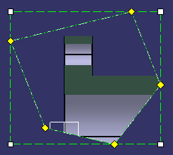
Polygonal profile:
-
Click in the geometry to select the first point and draw the profile as needed.
-
Double-click or select the first point to end the profile creation.
-
You can also enter the values for length in the L: box and angle in the A: box.

After selecting Clipping > Clip View, you can also select the Circular profile or Polygonal profile using the contextual menu (right-click in geometry).
-
-
-
Select the Polygonal profile and create the required clipping profile.
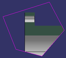
The handles are available to modify the clipping profile.
-
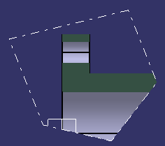
Click in the sheet to validate the profile.
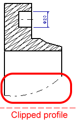
The view is clipped.
-
Right-click the clipped view in the tree or geometry and select Clipping > Modify Clipping.
The handles of the clipped profile become available.
-
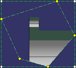
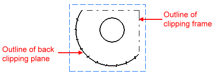
You can now reframe, resize, move the clipping frame, or add and remove control points according to your design needs.
- To manipulate the control points: Drag the yellow handles.
- To move the entire profile: Drag the frame itself using one of its green dotted lines.
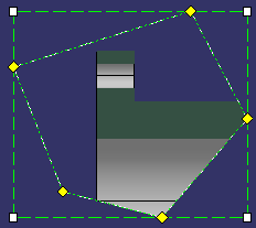
Option Description Resize:
Drag the white handles to resize the profile. The green dotted profile shows the resulting clipping after the manipulation.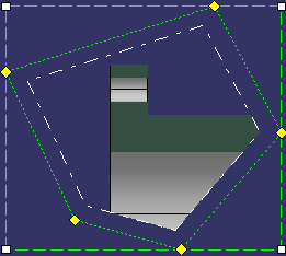
Remove Control Point:
Right-click the control point to be removed and select Remove Control Point.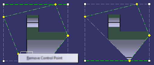
Add Control Point:
Right-click the clipping profile where the control point is to be added and select Add Control Point.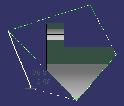
-
In addition, to change the color and line type of the clipping outline, right-click the view and select Properties > Visualization tab, under Clipping Outline.
- Clipping outline can be fully displayed or
invisible.
When displayed, the clipping outlines are also printed, and visualized in 3D (except if Hide in 3D option is selected). - Clipping outlines are non-selectable and therefore cannot be dimensioned or annotated.
- Visualization properties of clipping
outlines can also be customized from Tools > Options > Mechanical Design > 2D Layout
for 3D Design, View Creation tab, under Clipping
Outline.
For more information, refer to View Creation > Clipping Outline. - The visualization properties that can be
customized are:
- Display: Displays the clipping outline. By default, this option is selected.
- Color: By default, white color is selected.
- Line type (only among the first height line types): By default, line type is 4.
- Thickness: By default, thickness is 1.
- Clipping outline can be fully displayed or
invisible.
-
To unclip the clipped profile, right-click the clipped view in the specification tree or geometry, and select Clipping > Unclip View.
-
To replace the existing clipping view, right-click the clipping view in the specification tree or geometry, and select Clipping > Replace Clipping.
The previous clipping is removed and a new clipping can be defined in the same way as when using the Clip View command. The graphic properties of the replaced profile are applied to the newly defined clipping profile.
|
|
About Clipping View
-
If a clipping view is copied, the pasted view is a clipping view with the same profile as the copied view.
-
If a 2D layout view is created with the New View From command by selecting a clipping view, the new view is a clipping view in which the clipping profile is equivalent to the clipping profile of the reference view.
-
If a clipping view is rotated its profile is also rotated by the same angle.
If the view scale of a clipping view is modified, the position and size of the clipping profile are scaled too. -
When the clipped part is exported to a drawing, the representation of the generated clipping outline follows Generative Drafting options or Generative view styles, and thus may differ from 2D layout representation. If Tools > Options > Mechanical Design > Drafting > Administration tab, Generative view style area, Prevent generative view style usage option is cleared, you can select a predefined style when generating a single view or the default style (DefaultGenerativeStyle) is used when generating a full drawing. If Prevent generative view style usage option is selected, the linetype defined in Tools > Options > Mechanical Design > Drafting > View > View linetype is used.
- For pre-R18 2D layouts, where the view is not clipped, you can apply clipping to a view by using the Clip View command.
-
When pre-R18 2D layouts with a clipped view are exported to drafting and the drawing is updated, the representation of the generated clipping outline is also updated. The profile is updated as shown in the image:
Pre-R18 2D layout exported to drafting: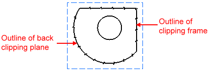
on updating drawing in R18:
The linetype used for clipping view in pre-R18 was of the breakout view. When exported to R18, the linetype used for clipping view depends on Generative Drafting options or Generative view styles, which is of detail view linetype.
![]()