This helps you locate a part in 3D, helps you visualize the assembly and how the drawings will look.
- Open a 3D shape representation. Ensure the view and the work on support are of the same 3D shape representation.
- To set up a 3D grid in 2D Layout for 3D Design, select a 3D grid or a 2D grid as a support for the 3D part. The grid that you set up can be both finite or infinite.
- If you select a 2D grid, ensure that the plane of the grid is parallel to the view support plane.
- In Tools > Options > 2D Layout for 3D Design > View Creation section > 3D Grid area, select the Display check box to display the 3D grid in the 2D layout. Select the Automatic Grid Size check box. Select other preferences for label position, font, font size, and grid overrun. For more information, see 3D grid. These properties decide the visualization of 3D grid when you create a view.
-
Create a view in the 2D layout window.
The view is created and the grid is displayed.
Notes: - The grid size is automatically adjusted. For both a finite or an infinite work on support grid, the 3D background 2D bounding box is the limit for the automatic size of the 3D grid. Since the default overrun size is 10mm, the grid is created at this distance.
- If no compatible work on support is detected for a view, the 3D grid is not created.
An infinite work on support 3D grid displayed at a default overrun of 10mm 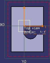
-
Right-click the view, and select 3D Grid > Edit Grid Size.
To edit the grid size, adjustable handles appear along the grid boundary.
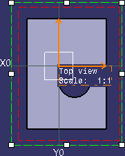
If the Automatic Grid Size option is selected, then selecting it again also sets the grid in edit mode. -
Click anywhere in the background after editing the grid.
-
Right-click the view, and select 3D Grid > Automatic Grid Size.
The default grid size is retained. -
For a finite grid, right-click the view, and select 3D Grid > Reset to 3D Grid Size.
The entire grid as visualized in 3D is displayed in the 2D layout view. -
Right-click the view, and select Properties.
The Properties dialog box appears. -
In the Visualization tab > 3D Grid section, edit the parameters, as required.
-
Click OK.
The parameters are edited and the grid is updated.
About Displaying 3D Grid in a View |
|
|