This topic provides information about the callouts created for
auxiliary views, section cuts, section views (including multi-plane
section views).
The following topics are discussed:
General Information
This sub-topic provides general information about callouts.
Callouts can be created at the time of view creation, in auxiliary views, section views and section cuts (including multi-plane section views/cuts). They can also be added to other views later on. Furthermore, the Locate Reference View and Locate Resulting View contextual commands enable you to navigate between auxiliary views, section views and section cuts and their reference callout views. For more information refer to Locating Reference/Resulting Views.
 |
The created callouts are automatically relimited on the 3D background
of the view in which they are placed. The callout relimitation is not
associative to the 3D background changes.
 |
 |
|||
| Profile to create the view |
Relimited Callout to 3D Background |
Callouts are created using the styles defined in
Projection Callout and
Section Callout in Tools > Standards..
(in the Standards Definition dialog box, select
Drafting category and the Standard_Name.xml file
according to the selected standard. Select Standard > Standard_Name
> Styles).
The property View Scale Dependant in the Projection Callout and Section callout style is not applicable to 2D Layout callouts or to the extracted 2D Layout callouts during generative view creation from a 2DL view.
You can edit callout properties by right-clicking the callout and selecting Properties and then the Callout tab.
Note: You cannot use the Graphic Properties toolbar to edit callout properties.
2D Layout callouts are processed similar to other annotations during the creation of a drawing view from a 2D Layout view. For more information about callout representation in drawing views, refer to More About Creating Drawings and Drawing Views From a Layout.
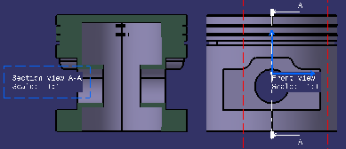
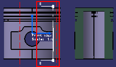
Callouts in the Case of Auxiliary Views, Section Views and Section
Cuts
This sub-topic provides information about callouts
created in the case of auxiliary views, section cuts, section views
(including multi-plane section views).
When creating auxiliary views, sections and multi-plane section views,
callouts are created in the reference view. In the context of this
topic, we will call this reference view the "callout view".
The callout view can be of the following types:
- Front, Left, Right, Top, Bottom, Rear,
- Auxiliary, Isometric,
- Section, Section Cut.
The callout view support plane is normal to the section/auxiliary view support plane.
When the view support plane is modified (for example using the Change View Support... command) or when the associated views are modified such that the callout view support plane is normal to the section/auxiliary view support plane, the callout is automatically updated and takes into account the changes (orientation, position, etc.). Note, however, that the callout's original length is not modified. If the update fails, the callout turns invalid and is displayed in the default invalid color. This color cannot be customized.
 |
|
|
Since associated views cannot be modified in the case of multi-plane section views, the above remark does not apply to callouts created in the case of multi-plane section views. |
About Callout Creation
- You can automatically create a callout in the active view when creating an auxiliary view, a section cut or a section view (including multi-plane section views) from a 3D plane, face, sketch, 2D layout view or Functional Tolerancing & Annotations view, using the New View From command (provided the Create callouts in active view at the end of "New View From" command option is selected in Tools > Options > Mechanical Design > 2D Layout for 3D Design > View Creation tab). For more information, refer to Customizing: View Creation.
- You can also add callouts in several types of views using the Create Callouts in Reference View contextual command. For more information, refer to Creating Callouts for Section/Auxiliary Views.
- To place the callout at the middle of the bounding box, select the Position callout of non-perpendicular view according to resulting view bounding box check box.
- The positions of the callout extremities are independent of the
modifications of the resulting view support plane.

It is applicable to the existing callouts: - If the existing callout is modified.
- If the plane of a view containing callouts is modified using the Change View Support command.
- If the plane of a view, having resulting callouts in other views, is modified.
Callout Size
- If the associated view is created from a 2D profile, the size of the callout is same as the 2D profile.
- In case its associated view is created from another element, the
callout size is computed according to this element:
-
If the element is a flat surface feature whose area is finite (fill surfaces or extruded surfaces…) the size of the callout is computed from the size of the surface projected as a line in the callout's view.
-
If the element is an infinite surface (3D plane…), a surface of feature (face of a pad…), a sketch, a layout view, a Functional Tolerancing and Annotation view or a Functional Tolerancing and Annotation capture, the size of the callout is computed from the extent of the 3D background of its view.
-
- If callouts are added after the view creation, the callout size computation is independent of the resulting view support axis system.
![]()