This task shows you how to create callouts for section views, section cuts or auxiliary views.
Open a .CATPart document. Double-click Sheet.1 in the
specification tree to open the layout in the 2D window.
Create a section view, section cut or auxiliary view.
Create Callouts in a Reference View
-
Right-click the section/auxiliary view and select Section/Auxiliary object.xxx > Create Callout in Reference View.
-
Select a suitable parent view to create the callouts.
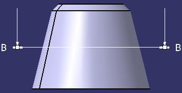
The callout is created.

- The callout is automatically relimited on the 3D background of the view in which it is placed.
- To locate the resulting view, right-click the callout and select Locate Resulting View.
Edit Callouts
|
|
|
-
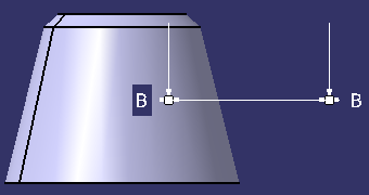
Double-click the callout to change it to edition mode.
-
Perform any one of the following operations:
-
- Drag the handles to the required position.
- Click in the layout to validate.
-
- Double-click the handles or right-click a handle and select Definition.
- In the Point Definition panel, specify the required values and click OK.
When you edit an existing profile, you can now precisely manipulate the control points of the following by using SmartPick or defining the exact location of points: a profile of callout, a clipping, a clipping frame, or an isolated area fill. -
Reset Callouts
-
Right-click the callout which you want to reset.
-
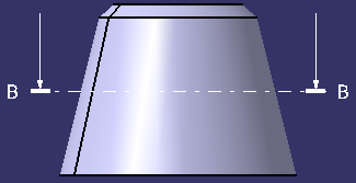
Select Reset Size and Position.
The callout is reset to the standard size and position.
Position Callout Texts Manually
|
|
The contextual menu is accessible when the pointer is over callout representation or callout texts. |
-
Right-click the callout text and select Position Texts Manually.
An outlined box with a solid line type is displayed on the selected callout texts. This indicates that the callout text is in manual positioning mode. It is now possible to move the callout text anywhere by dragging it.

-
Drag the selected callout text to the required position.

|
|
|
![]()