This task explains how to process geometry for a more efficient data management.
To address the data management process in a more efficient manner, ISD commands must be designed in a way that they can handle data coming from everywhere.
Within the Class A process, the more traditional approach for users is to obtain geometry output of a maximum order 7 and by having less segments and with a minimum Deviation from the original Input geometry. As this is not always possible users prefer to have better control over the output.
Open the ConversionSurface.CATPart document.
-
Click the Surface Conversion icon
 .
.
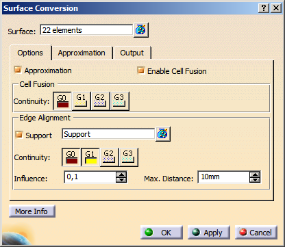
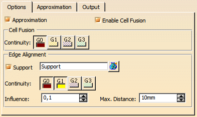
The Surface Conversion dialog box opens.
-
Select the surfaces 1 to 7.
-
Select Enable Cell Fusion and Continuity: G0 on the Options tab.
-
Select Single-Result on the Output tab.
-
Click OK to convert the surface cluster into a single-cell surface.
- Surface: Specifies the surfaces to be processed.
Only surfaces trimmed at iso-curves are allowed for selection.
- Approximation: The approximation options can be deactivated. This way, you can e. g. create curves from surface edges without approximation.
- Enable Cell Fusion:
- OFF: Each cell of a Domain will be approximated separately.
The Cell Fusion options are not available. - ON: All adjacent cells of a domain whose transition quality among each other corresponds at least the value specified
in Continuity, are approximated as one entity (segmentation of the domain in continuity ranges).
The Segmentation will be applied to each continuity range.
The transition parameters will be used as preferential parameters for further processing with the settings on the Approximation tab.
- OFF: Each cell of a Domain will be approximated separately.
- Cell Fusion - Continuity (G3 in ISD only): The
Cell Fusion options are only available if Enable Cell Fusion is selected.
The cells are only merged if at least the specified continuity is kept.
To keep the number of segments as low as possible, when using G0 continuity, the tolerance will not be considered when approximating, independently from the approximation parameters set. - Edge Alignment: Only available if Support check box is selected and support surfaces are selected.
You can align the converted surface result to the selected support surfaces by imposing continuity conditions along the edges of the converted surfaces.- Support: Select support surfaces.
- Continuity: Aligns the converted surfaces to the support surfaces with the selected continuity.
- Influence: Specifies how much the converted surfaces are influenced by the alignment of the support surfaces.
- Max. Distance: The support surfaces are used for edge alignment, if the distance between edges of the selected surfaces and the support surfaces is smaller than the specified value.
In addition to the general approximation options, the following Parametrization methods are available on this tab:
- Curvature: The parametrization is calculated from the curvature distribution of the input surface.
- Average: The parametrization is calculated from the spatial deformation (Arc Length) and the curvature distribution (Curvature) of the input surface.
With the parametrization methods Curvature and Average, shape and control point distribution of the result surface can be optimized. The following example shows the results created with the parametrization methods Arc Length and Curvature:
| Conversion of a multi-segment spline surface to a single-segment surface | |
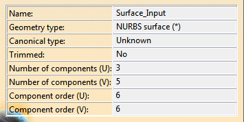
input surface |
 |
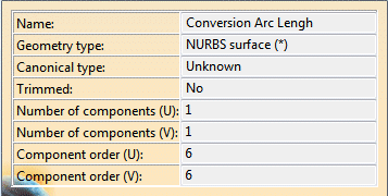
| Conversion with parametrization method Arc Length | |
 |
 |
| The deviation of the result from the input surface is within the allowed tolerance. However, the conversion result shows unwanted inflections at the indicated locations. |
|
| Conversion with parametrization method Curvature | |
 |
|
| The accuracy of the result surface is within the specified tolerance. The conversion result reflects the shape of the input surface without inflections. |
|
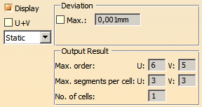
- Display: Depending on the options selected, values are displayed in the graphics area.
- U+V: Display of the UV vectors of curves and surfaces.
- Static, None: See Apply Modes
- Deviation:
- Max.: Shows the maximum deviation between the input element and the resulting output geometry, e. g. between
a guide curve (input) and the resulting surface boundary (output).
Depending on the result you can change parameters and options to improve the resulting geometry.
- Max.: Shows the maximum deviation between the input element and the resulting output geometry, e. g. between
a guide curve (input) and the resulting surface boundary (output).
- Output Result: See Output Result