 |
This task explains how to generate a blend surface between
surface edges or curves on surfaces.
|
 |
The connecting edges may consist of several edges or curves. If no support
is used, the result will be created with G0 continuity between blend and
connecting surfaces. Additionally, curves or edges can be projected onto
surfaces. In this case, the blend surface will be matched to the projected
surface curves. If a support surface is selected, the transition quality
may be position, tangent, curvature, or torsion continuity (G0-G3).
The beginning or end cross tangent of the blend surface can be aligned
collinear to the beginning or end cross tangent of the adjacent surfaces.
For the blend type 'Global', the iso-curves of the blend surface
can be aligned by a moving frame. Depending on the transition quality of
the adjacent surfaces between each other, the blend surfaces are matched
to each other meeting tangent or curvature continuity. The segmentation
of the blend surface depends on the segmentation of the edge selected first.
The start and end points of the connecting edges can be re-defined subsequently.
Move the point manipulators at the start and end along the selected edges
(see also Manipulators and contextual commands).
|
| |
Creation of a blend surface (blend type 'Global')
|
|
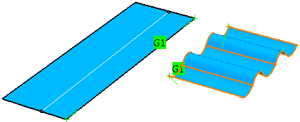
In the following example, a blend surface will
be created, one of the connecting edges consisting of several elements. |
 |
Open the Blend.CATPart
document. |
 |
-
Click the Blend Surface icon
 . .
The 'Blend Surface' dialog opens.
|
|
| |
-
Select an edge of Surface 1 as first connecting
edge ('Side 1').
Surface 1 is automatically selected
as Support 1.
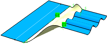
-
Select edges of Surfaces 2 to 6 as second connecting
edge ('Side 2').
The surfaces 2 to 6 are automatically
selected as Support 2.
|
 |
| |
-
Click 'Apply'.
The blend surface is calculated
with G1 continuity.
|
 |
| |
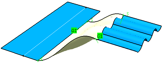
-
Move the point manipulator at start 'S'
of 'Edge 1' along the edge.
The connecting edge will
be shortened, and the blend surface will be re-calculated accordingly.
|
 |
| |
-
Click 'OK'.
The blend surface will be
created as a feature.
|
 |
You can define the following options: |
| |
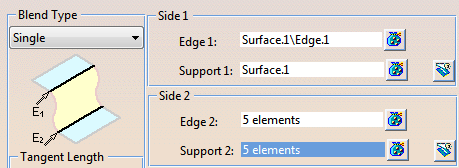
- Blend type
 |
Single |
Creation of a blend surface with the options
of the 'Options' and 'Coupling' tabs.
2nd Curve is automatically
used as moving frame. |
 |
Global |
The 'Moving Frame' tab is additionally
available for aligning the iso-curves of the blend surface.
The 'Coupling' tab is only available, if
2nd Curve is selected
as moving frame type. |
- Tangent length: The control point distribution may be
controlled via the inner tension manipulators. For computing the
cross tangent lengths, the following modes are available:
- Auto : Automatic computation of the tangent lengths.
- Constant : Use of a constant length as master
for all other tangent lengths.
- Ratio : Adaptation of the second and all following
control point segments (depending on the set continuity)
to the first control point segment. This will be done by
assuming that the length ratio between the first and the
second control point segment is the same as the length ration
between the second and the third one, and so on.
|
| |
- Side 1/Side 2:
- Edge 1/2: Select 1st and 2nd connecting edge.
By default, the edge selected first will be used as spine
curve for defining the moving frame. You can, however, select
any other curve as spine curve (see
'Moving Frame' tab).
If an offset or iso-parametric curve is selected as input
element, certain parameters of these curves can be modified
via manipulators directly in the Blend Surface
command (see Curve offset
and isoparametric curve as input features).
- Support 1/2: Blend patches
into the inside of a surface can be created using this option.
For this, existing curves from Edge 1 and Edge 2 are projected
onto the supports in patch normal direction to generate
surface curves. These curves are then used as connecting
edges.
If no support is used, the result will be created with G0 continuity.
If a support surface is selected, the Continuity
can be G0, G1, G2, or G3.
|
| |
'Options' tab |
 |
| |
For both Side 1 and Side 2
you can define the following options:
- Continuity
- G0, G1, G2, G3 (G3 in ISD only): Controls
the transition quality between blend and adjacent surfaces
for the two connecting edges.
These options are only
available if Support is activated.
| Continuity =
G0
|
Continuity =
G1
|
Continuity =
G2
|
Continuity =
G3
|
|
| |
 |
Alignment: These options can be used for controlling
the distribution of the control points of the blend surface.
For the modes 'Edges Start/End', 'All Edges' and 'Auto',
the start and end tangents can be modified via the manipulator.
When using these options, the inner cross tangents will be propagated.
As the direction of the cross tangents is fixed when using the alignment
modes 'Standard' and 'Linear', the start and end
tangents cannot be modified.
- Standard : Corresponding points on all blend
edges at 'Side 1' and 'Side 2' are connected
via a line. The direction of this line is projected onto
the tangent plane at the specific position of the edge.
This projected direction is used as a U tangent of the blend
surface at the specific edge point.
Edge continuity cannot be
defined.
| Alignment: Standard |
 |
- Edges Start/End
: Existing cross edges of the support at 'Side
1' and/or 'Side 2' are continued. The direction
of the cross tangents within the specific edge will be spread
over the whole edge (with respect to isolines).
Edge continuity can be defined.
| Alignment: Edges Start/End |
Alignment: Edges Start/End – Distribution
of tangents |
 |
 |
- All Edges : All edges of the support crossing
the blend edge are continued. The cross tangent directions
will be propagated over the edge (with respect to isolines)
until a segment border is reached.
Edge continuity cannot be
defined.
| Alignment: All Edges |
Alignment: All Edges – Distribution
of tangents |
 |
 |
- Linear: Cross isolines will be continued if the
edge is adaptable the U or V isoline of the support.
Edge continuity cannot be
defined.
| Alignment: Linear |
 |
- Auto: Automatic distribution
of the cross tangents.
Edge
continuity can be defined.
| Alignment: Auto |
 |
|
|
| |
|
|
Edge continuity (G3
in ISD only):

 Aligns the beginning and end cross tangents at the edges of the
blend and adjacent surfaces.
Aligns the beginning and end cross tangents at the edges of the
blend and adjacent surfaces.
Edge continuity can be defined for
the 'Alignment' modes EdgesStart/End
and Auto.
- Start and End continuity OFF: The
beginning and/or end cross tangents will be aligned coplanar
only, i. e. there may be an angle between the cross tangents
of the blend and adjacent surfaces.
- Start or End continuity ON: The beginning
or end cross tangent of the blend surface will be aligned
collinear to the beginning or end cross tangent of the adjacent
surfaces.
- Start and End continuity ON: All cross
tangents of the blend surface will be aligned collinear
to the cross tangents of the adjacent surfaces.
|
|
| |
- Trim Type: The underlying support surfaces can be trimmed
at the connecting edges of the created blend surface.
 Creation of approximated surfaces.
 Creation of trimmed surfaces.
|
| Result without trimming |
Result with trimming |
 |
a) with option
b) with option
|
|
| |
See 'Moving Frame'
tab (in ISD only) |
| |
'Coupling' tab |
 |
| |
The Coupling tab is only available in conjunction with the option
2n Curve on the Moving Frame tab.
It is used to influence the moving frame in order to obtain an optimal result
independent from the structure of the original geometry.
- Coupling: The coupling functionality can be switched
on and off.
- OFF: If edge 1 and 2 have the same number of segments, the
segmentation is decisive for the Blend Surface calculation,
i. e. the segment boundaries will be taken from the original
geometry.
If the segmentation is unequal, the total arc length
of the edges will be used for the segmentation calculation.
- ON: The segmentation is calculated according to the arc
length. The arc lengths of edge 1 and 2 are determined and
on edge 2, the segment boundaries are inserted at the points
whose distance value from the start and end points of edge
2 have the same ratio to the total arc length as on edge
1.
If no coupling is defined, the total arc length will
be used for the segmentation calculation.
If one or several couplings are defined, for the segmentation
calculation will be used the arc lengths of the sections
defined by the coupling vertices.
 |
Note: The coupling
vertices can be selected arbitrarily. However, they
should lie on the edges of the original geometry
and be selected in succession of their positions.
|
- Force G1 in edge direction :
- OFF: The continuity of the selected supports and
the coupling conditions imposed by the user will be inherited
for the result surface.
- ON: The surface blend attempts to override and remove
any internal G1 patch discontinuities.
- Display: The defined couplings are displayed as lines.
- Coupling table:
- X: A defined coupling can be deleted.
- Coupling: Display of the defined couplings.
- Edge 1/2: Display of the selected coupling vertices
on edge 1 and 2.
The selection can be changed after clicking
onto a coupling vertex in the table.
- Coupling Vertex: For the current coupling can be either
selected existing points as coupling vertex or new points created
via the contextual command.
|
|
See 'Approximation'
tab |
 |
| |
In addition to the general options for the
approximation, the following options are available on this tab:
- Blend Surface Segmentation
- Sep. Spine: The segmentation is taken from the
curve selected under
Separate Spine
on the 'Moving Frame' tab.
- Sep. Spine and Side 1: The segmentation is taken
from the curve selected under
Separate Spine
on the 'Moving Frame' tab and Side 1.
- Sep. Spine and Side 2: The segmentation is taken
from the curve selected under
Separate Spine
on the 'Moving Frame' tab and Side 2.
- All: The segmentation is taken from the curve
selected under Separate
Spine on the 'Moving Frame' tab and Side 1 and
2.
|
| |
See 'Output'
tab |
|
Click 'More Info'
to display deviations and output results. |
 |
| |
- Display: Depending on the options selected, values are
displayed in the graphics area.
- Deviation (Side 1 and 2): Maximum deviation between the
edges of the created surface and the connecting edges.
- Check buttons: The maximum deviation can be displayed
in the graphics for each side.
- G0 - G3 (G3 in ISD only): Display of the
maximum deviation in the dialog box.
- U+V: Display of the UV vectors of curves and surfaces.
- MFT: Display of the local coordinate system for the moving
frame type.
- Dynamic, Static, None: See
Apply Modes
- Output Result: See Output Result
|
| |
Curve offset and isoparametric curve as
input features
If an offset or isoparametric curve is selected as input element, certain
parameters of these curves can be modified via manipulators directly in
the command Blend Surface.
For offset curves, length manipulators are displayed at the curve’s
start and end. For isoparametric curves, a point manipulator is shown directly
on the support surface.
Explicit creation of input features
The following prerequisites apply to the use of these features as input
elements:
- The input features must have been created with the commands
ISD Curve Offset or GSD Isoparametic Curve.
- The support surface for creating the blend surface must be the same
used for the input feature. The size of the support surfaces must
be identical.
- The offset curve must have been created with Alignment: On
Surface. The option Both Sides must be switched
off.
Implicit creation of an isoparametric curve
Instead of creating an external isoparametric curve it is also possible
to internally create such a curve inside the Blend Surface command
which simplifies the workflow drastically.
After starting the function command, the selection of the edges and support
elements will be activated. When the
mouse pointer is positioned on top of a surface, the preview of an isoparametric
curve is shown at the pointer position. By pressing the left mouse button,
the curve will be created. This curve will then be added to the list of
edges, and the selected surface to the list of supports.
The border curve of the support which is closest to the picked position
will be taken to align the isoparametric curve (U or V direction).
|
| |
Manipulators at input features
The following manipulators are available:
|
| |
Length manipulators for controlling the curve offset
distance
 |
Point manipulators for controlling the isoparametric
curve position
 |
| |
Manipulators and contextual commands
The created blend surface can subsequently be modified by point and continuity
manipulators. At the manipulator handles, you can activate with the right
mouse button contextual commands with the following options:
|
| |
- Edit : Modifies the relative manipulator position via
dialog box 'Tuner'.
- Keep this point: Creates a point at the current position
of the manipulator.
- Swap UV: The parameter direction of the curve is swapped.
- Snap to border : The curve is snapped to the closer border
in that parameter direction.
- G0, G1, G2, G3 : Sets the specified continuity.
|
 |
|

|