|
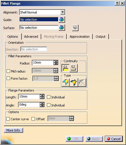
You can define the following options:
- Alignment: The basic flange direction runs
- in normal direction of the base surface, if surface edges have been selected as guide curve, or
- in normal direction of the target surface, if the guide curve is a curve segment or curve.
Basic flange direction is the direction of the flange at an angle of 0°.
- Guide: Select one or several guides. Following elements can be selected:
- Surface:
- Alignment Shell normal selected: Selects a surface or plane whose normals in the points
of the guide define the basic flange direction.
- Option Offset selected: Selects a target surface or plane at which the fillet flange surface
starts.
 Trim surface:
Trims the surfaces at the fillet edge. Trim surface:
Trims the surfaces at the fillet edge.
|
| |
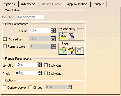
'Options' tab |
 |
| |
- Orientation: This option is only available for Guide + prio. tangent and
Guide + prio. direction.
- Direction: Specifies the flange direction by selecting an element or via the contextual command.
- Fillet Parameters:
- Radius: Defines a global radius value across the full length of the fillet.
- Mid radius: Only available if Form factor is cleared.
For the middle of the arc can be specified a mid radius different from the Radius.
The transition quality will be preserved.
The mid radius is applied along the center line of the radius value.
- Form factor: Only available if Mid radius is cleared.
Determines whether the fillet shall be more flat or more copped. The transitions to the original
curves remain unchanged.
Values smaller than 1 create flat fillets, values higher than 1 steep fillets.
| Form Factor cleared |
 |
| Form Factor 0,5 |
Form Factor 2,0 |
 |
 |
- Continuity: Two continuity settings are available for the resulting fillet:
 : Tangency continuity is maintained between fillet
and support surfaces. : Tangency continuity is maintained between fillet
and support surfaces. : Curvature continuity is maintained between fillet
and support surfaces. : Curvature continuity is maintained between fillet
and support surfaces.
- Type
 Variable Radius:
Defines several different radii along the guide curve. Variable Radius:
Defines several different radii along the guide curve.
In addition to the two manipulators representing the fillet radii at each end further manipulators can be inserted to
define several different radii at the manipulator positions. This way, a variable fillet of a linear transition can
be created. Chordal Fillet:
Only available if Variable Radius is cleared. Chordal Fillet:
Only available if Variable Radius is cleared.
A fillet with chordal parametrization and constant distance across the bi-tangent lines of the fillet is created. True
Minimum Radius: Only available for G2 continuity. True
Minimum Radius: Only available for G2 continuity.
Minimum radius is controlled. Trace curves will be computed 1.5 x Mid Radius value for G2.
When activating the icon, True Minimum Radius is displayed instead of Radius.
- Flange Parameters:
- Length: Defines the main length of the flange.
- Individual: You can specify an individual length between start and end point.
- Angle: Defines the angle of the flange with respect to the selected alignment options.
- Individual: You can specify an individual angle between start and end point.
|
| |
For the options Length and Angle the following contextual menu is available:
- Change step: The values for Length and Angle can be modified by 1 mm or the specified step size. The step size
can be modified via new one.
- Measure between... : see Measuring
Distances between Geometrical Entities.
- Measure Item...: see Measuring Properties.
- Add Range: For Length and Angle, you can specify values within a range.
With this option a dialog box is activated, in which you can modify the values for the inferior and superior range. With the
option Included, the inferior and superior limit values are included.
|
| |
- Options:
- Center curve: Creates a 3D curve passing through the center of the fillet portion of the fillet flange surface.
- Offset: Offsets the fillet portion of the fillet flange by a specific value.
With the offset value 0, the cross tangents of the flange meet the guide.
In addition, you can select via Surface a target surface or plane at which the fillet
flange surface starts.
| Offset cleared |
 |
| Offset = 0mm |
Offset = 7mm |
 |
 |
|
| |
'Advanced' tab |
 |
| |
- Type:
- None: Creates the flange with the specified Length.
- Connect: The flange length is limited at the surface to be selected with Reference. If
Connect is selected, Individual is not available for Length.
|
| |
- Shape: Influences the flange shape, if the flange has at least one inner manipulator and individual values
are set for Length or Angle.
If the check box Shape is cleared, the setting Smooth Shape is used as default.
|
|
Linear Shape
|
Local Shape
|
|
Smooth Shape
|
Global Shape
|
|
|
| |
See Moving Frame tab |
| |
See Approximation tab |
| |
See Output tab |
| |
Click 'More Info' to display deviations and output results. |
 |
| |
- Display: Depending on the options selected, values are displayed in the graphics area.
- U+V: Display of the UV vectors of curves and surfaces.
- MFT: Display of the local coordinate system for the moving frame type.
- Dynamic, Static, None: See Apply Modes
- Deviation:
- G0, G1, G2: Displays the maximum continuity deviation of the Fillet result measured against the support surface
as a result of the approximation settings imposed.
- Output Result: See Output Result
|
| |
Manipulators and contextual commands
|
| |
The created flange surface can be modified as follows using the manipulators:
Moving the drag manipulator on the guide, you can add additional manipulators allowing to specify individual lengths and angles:
|
 |
Note: Pressing the control key allows simultaneous manipulations of length and angle. In this case,
however, individual values will be equated. |
| |
- Invert direction: Upon the selected guide curve a moving frame type manipulator is displayed. By selecting either
the X (yellow) or Y (blue) manipulator, the user can select which quadrant of the created flange is
required.
|
| |
At the manipulator handles, you can activate with the right mouse button contextual commands with the following options:
- Edit: The parameter value can be modified in the dialog box Tuner.
- Spread all: The current value is assigned to all other manipulators.
- Keep this point: A point is created at the current position of the manipulator.
- Delete (for additionally inserted manipulators only): Deletes the manipulator.
|
 |
|

|
 .
.
 in the Tools Dashboard to display the control point mesh temporarily to check the result.