|
This task explains how to create a flange from a reference curve. |
 |
Flange surfaces are composed successively from ruled surfaces.
A flange surface can start from the guide curve or from a target surface. Length and Angle define extent and direction of the
flange surface. The basic flange direction is the direction with a flange angle of 0°.
The order of the flange surface in direction of the guide curve
will be adopted from the guide curve. The order perpendicular to the guide curve will always be 2. The guide curve
- can exist for itself, without a surface, 3D-Curve
- can be connected with a surface, 2D-Curve
- can be the edge of a surface
|
 |
Open the Flange.CATPart document. |
 |
-
Click the Flange icon  . .
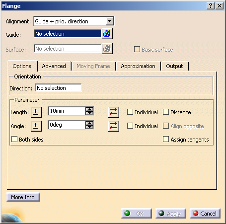
The Flange dialog box opens.
|
|
| |
-
Select the edge of the surface where you want to create the flange.
|

|
| |
-
Select as Alignment Patch Normal and Surface.1 as reference Surface.
-
Enter a Length of 100mm and click Apply. The flange surface and two vectors
are displayed.
|
 |
| |
-
Change the angle by drawing the first handle at the manipulator tip.
|
 |
| |
-
Change the length by drawing the second handle at the base of the manipulator tip.
|
 |
| |
-
Invert the flange direction by clicking onto the middle handle of the manipulator.
|
 |
| |
-
Undo the inversion. Click into the middle of the guide and move the pointer to insert another manipulator.
|
 |
|
-
Activate the Individual options for Length and Angle.
-
Specify an individual length and angle by modifying the middle manipulator.
|
 |
| |
-
Click OK to create the final flange surface.
|
 |
 |
You can define the following options:
- Alignment: The basic flange direction runs
- in normal direction of the base surface, if surface edges have been selected as guide curve, or
- in normal direction of the target surface, if the guide curve is a curve segment or curve.
- Shell normal: The basic flange direction runs in direction of the normals in each
point of the guide on the selected surface.
If the guide does not lie on the surface, it will be projected normal onto the surface, and the normals in the projected
points define the basic flange direction.
- Guide + prio. tangent: The basic flange direction is generated from a moving
frame type that is aligned by the normal plane in each point of the curve and by the Direction defined in the
'Orientation' box. The moving frame type runs tangentially to the guide and thus may define a different flange direction
in each curve point.
- Guide + prio. direction: The basic flange direction is defined by a moving
frame which is only aligned by the Direction specified in the 'Orientation' box without taking into account
the curve tangent or normal plane. The basic flange direction is equal in each curve point.
- Moving Frame: The flange direction can be defined by a Moving Frame (see 'Moving
Frame' tab).
- Guide: Select one or several guides. Following elements can be selected:
- Surface: The following options are only available for Shell normal.
Select one or several surfaces or planes, whose normals specify the basic flange direction in the points of the guide.
- Basic Surface: If a guide is projected onto a face selected as support and the result lies in the trimmed
area of the face, the flange will not be completely computed along the guide.
- ON: The guide is projected onto the basic surface of the faces.
- OFF: The guide is projected directly onto the selected faces.
 |
Note: The projection of the guide onto the underlying surfaces of faces is only possible in case
of support surfaces being selected with 'Surface' for 'Alignment: Shell Normal', but not onto faces selected as target
surfaces with Target on the 'Advanced' tab. |
|
|
| |
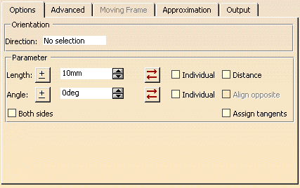
Options tab |
 |
| |
- Orientation: This option is only available for Guide + Prio. Tangent and
Guide + Prio. Direction.
- Direction: You can specify the flange direction manually via the contextual menu.
- Length: Defines the main length of the flange.
 Invert direction: Inverts the direction. The
Length values are also inverted. Invert direction: Inverts the direction. The
Length values are also inverted. Revert direction: Inverts the direction only. The
Length values remain unchanged. This allows, for example, to use positive values only. Revert direction: Inverts the direction only. The
Length values remain unchanged. This allows, for example, to use positive values only.
|
Note: Invert direction and Revert direction cannot be used individually, i.
e. the direction is also modified on the opposite side as well as for Factor and
Angle. |
- Individual: You can specify an individual length between start and end point.
- Distance:
- ON: The flange surface will be created in flange direction. The flange length is measured along the basic
flange direction.
- OFF: The flange surface will be created in flange direction. The flange length is measured along the defined
flange direction.
- Angle: Defines the angle of the flange with respect to the selected Alignment options.
- Invert angle: Inverts the angle. The Angle
values are also inverted.
- Revert angle: Inverts the angle only. The
Angle values remain unchanged. This allows, for example, to use positive values only.
|
Note: Invert angle and Revert angle cannot be used individually, i. e. the
angle is also modified on the opposite side as well as for the crown options Factor and
Angle. |
- Individual: You can specify an individual angle between start and end point.
- Align opposite: If Both sides and Individual are switched on for Angle,
the opposite angle can be aligned. That means the difference between both angles is always 180°. In this case, only one
flange surface is created.
- Both sides: Creates a flange surface in both directions of the flange alignment.
- Assign tangents: At the opposite edge of the flange surface the tangent will be adopted at both ends from the
guide.
|
| |
For Length and Angle the following contextual menu is available:
- Edit formula...: Enables you to edit a formula, see
About the Formula Editor.
- Add tolerance...: Enables you to edit tolerances.
- Change step: The values for Length and Angle can be modified by 1 mm or the specified step
size. The step size can be modified via new one.
- Measure between... : see Measuring
Distances between Geometrical Entities.
- Measure Item...: see Measuring Properties.
- Add Multiple Values...: Enables you to add multiple values for the object.
- Add Range...: For Length and Angle, you can specify values within a range.
Activates a dialog box in which you can modify the values for the inferior and superior range. With Included, the
inferior and superior limit values are included.
- Edit Comment...: Enables you to add a comment.
- Lock: Enables you to lock a parameter.
|
| |
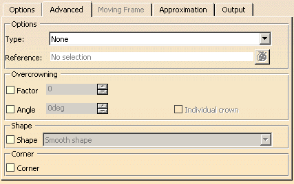
Advanced tab |
 |
| |
- Type
- None: Nothing is defined.
- Target: The flange surface starts from a target surface to be selected via Reference.
The resulting flange is moved to the target surface. Guide and angle are used as input parameters.
- Connect: The resulting flange ends on the selected Reference. The reference element can be a surface
or a plane.
- Overcrowning (in ISD only): The created flange surface can be overcrowned either
by specifying a crown factor or a draft angle.
When Overcrowning is selected, Both sides is disabled.
- Factor: The crown height at the mid point of the flange is the result of the multiplication
of crown factor and length of the flange (not overcrowned).
- Angle: The draft angle is the angle by which the tangent is rotated at the flange
end.
- Individual Crown: The draft angle can be specified individually for each point using the manipulators.
|
| |
- Shape (in ISD only): Influences the flange shape, if the flange has at least one inner manipulator and
individual values are set for the parameters Length, Angle, or
Overcrowning.
If the Shape check box is cleared, Smooth Shape is used as default.
|
|
Linear Shape
|
Local Shape
|
|
Smooth Shape
|
Global Shape
|
|
|
| |
- Corner: If a complex guide curve is selected, which consists of connected lines and fillet arcs, the flange has
no G2 continuity between the separate parts.
This option allows to calculate a flange with corner surfaces to obtain a smooth control point mesh at corners where the different
parts have G2 continuity.
|
Note: In the Analysis area, the option Corner must be active. |
First a symbol at the edge u = 0 is created on the guide side for each cell.
After selecting a symbol and clicking Apply, the following manipulators are created at the opposite edge of the
selected symbol:
- Continuity manipulators: Clicking onto the continuity manipulators toggles between G1 and G2 continuity.
- Tension manipulators: Moving the tension manipulators modifies the tension factor as well as all control
points except those at the guide edge.
|
Note:
- The continuity and tension manipulators are only displayed if 'Continuity'
 and 'Tension' and 'Tension'
 in the
Tools Dashboard are switched on. in the
Tools Dashboard are switched on.
- A corner can only consist of one cell.
- The start and end cells of a wire are not allowed to be selected as corner cells.
- Also adjacent cells to a cell selected as corner are not allowed to be selected as corners.
|
|
| |
See Moving Frame tab (ISD only) |
| |
See Approximation tab |
| |
See Output tab |
| |
Click 'More Info' to display deviations and output results. |
 |
| |
- Display: Depending on the options selected, values are displayed in the graphics area.
- U+V: Display of the UV vectors of curves and surfaces.
- MFT: Display of the local coordinate system for the moving frame type.
- Corner: The display of the corner manipulators can be switched on and off.
- Invert: The display of the manipulators for inverting the direction of individual wires in the selection of guide
curves can be switched on and off.
If a selection includes several wires (e. g. the selection of profile or guide curves), the direction of the individual wires
influences the result calculation.
The invert manipulators make the intrinsic wire flow direction of the selected wires visible and allows to invert the direction
of individual wires in order to obtain an optimal result. Example:
| Guide selection without manipulators |
|
| Guide selection with manipulators and display of the intrinsic flow |
The manipulator shows the intrinsic flow direction per wire (display color: green).
|
| Guide selection with manipulators and inverted flow |
Clicking the middle manipulator handle inverts the direction (display color: red).
|
- Dynamic, Static, None: See Apply Modes
- Deviation:
- Guide: Displays the deviation of the approximated guide.
- Shape: Displays the deviation from the flange.
- Output Result: See Output Result
|
| |
Manipulators and contextual command
|
| |
The created flange surface can be modified as follows using the manipulators:
Moving the drag manipulator on the guide, you can add additional manipulators allowing to specify individual lengths and angles:
The flange surface can be restricted to a partial region:
|
|
Note: Pressing the control key allows simultaneous manipulations of length and angle. In this case,
however, individual values will be equated. |
| |
At the manipulator handles, you can activate with the right mouse button contextual commands with the following options:
|
| |
- Edit: The parameter value can be modified in the dialog box 'Tuner'.
- Keep this point (for angle modification only): A point is created at the current position of the manipulator.
- Spread all (for angle and length modification only): The current value is assigned to all other manipulators.
- Delete (for additionally inserted manipulators only): Deletes the manipulator.
- Invert: Direction or angle will be inverted. Corresponds to the options 'Invert direction/angle'
for Length and
Angle.
- Revert: Direction or angle will be reverted. Corresponds to the options 'Revert direction/angle'
for Length and
Angle.
|
 |
|

|