If Approximation is switched on, in the second step a 3D curve will be approximated from the result from step one according to the parameters set in the Approximation tab.
-
Click the Intersection icon
 .
.
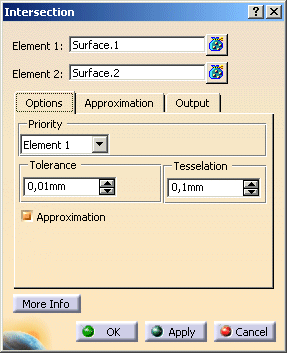
The Intersection dialog box opens.
-
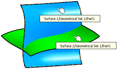
Select Surface.1 as first element and Surface.2 as second element.
-
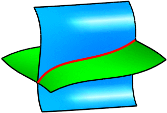
Click OK to create the intersection element.
This element (identified as Intersect.xxx) is added to the specification tree.
- Element 1, Element 2: Selection of elements between which the intersection curve shall be created. You can select surfaces and/or point clouds.
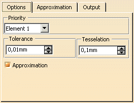
- Priority: Element 1, Element 2: If only surfaces have been selected, you can specify
with this option on which surface the surface curve shall be created.
If surfaces as well as point clouds or point clouds only are selected, this option has no impact. - Tolerance: This value defines the admissible deviation of the surface curve from the surface without priority.
The examples below show the impact of different tolerance values used. In both examples the result oscillates more or less within the specified tolerance.

This option has no impact if one of the element sets contains at least one point cloud.
The tolerance will have a direct impact upon the complexity of the result in either approximated or non approximated results, as it will depending upon the tolerance value, increase the segmentation and order of the result in order to achieve the desired tolerance.
The examples below show the impact of different tolerance values used. In both examples the result oscillates more or less within the specified tolerance. - Tessellation: This tolerance value is used if an intersection shall be calculated between surfaces and point
clouds. It defines the admissible deviation of the surface curve from the point cloud.
This option has no impact if one of the element sets contains at least one surface.
| Note: The tolerance will have a direct impact upon the complexity of the result in either approximated or non approximated results, as it will depending upon the tolerance value, increase the segmentation and order of the result in order to keep the desired tolerance. |
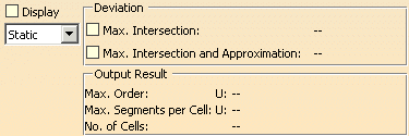
- Display: Depending on the options selected, values are displayed in the graphics area.
- Static, None: See Apply Modes
- Deviation:
- Max. Intersection: Display of the maximum deviation of the surface curve from the surface without Priority.
- Max. Intersection and Approximation: Two intersection curves are calculated with
Approximation ON and with Approximation OFF.
The maximum deviation of the surface curve and the approximated 3D curve from the surface without Priority is calculated and the higher deviation displayed.
- Output Result: See Output Result
![]()