If the curve is a 2D curve or a surface edge, the offset curve can be created on the 2D curve or the surface, and the distance can be measured on the surface.
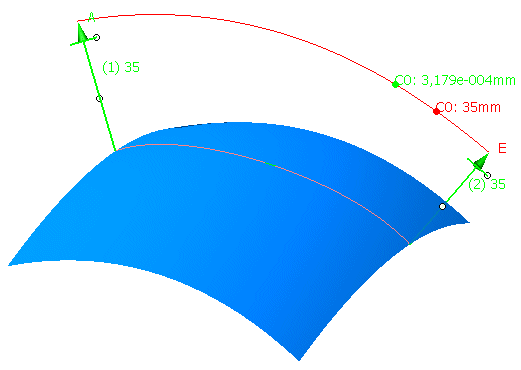
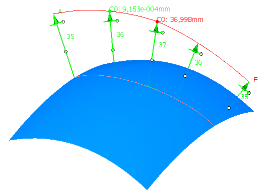
By switching on the option 'Individual', the vectors can be manipulated separately.
-
Click the Curve Offset icon
 .
.
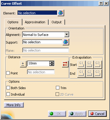
The 'Curve Offset' dialog box opens.
-
Select Curve.1, choose the Alignment Option Normal to Surface and select Surface.1 as Support.
-
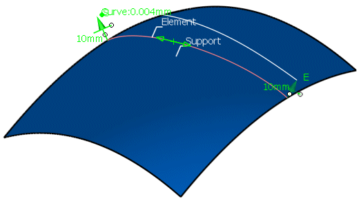
Press 'Apply' to display the offset curve.
-
Change the offset distance either by
-
drawing one of the handles at the end of the manipulators or
-
via the option 'Edit' in the contextual menu.
-
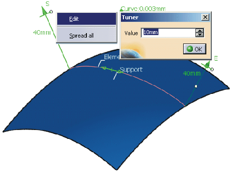
-
Click 'OK' to create the offset curve.
- Element: Selection of the curve to be offset.
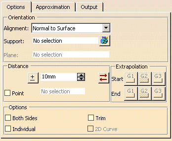
- Orientation
- Alignment: Definition of the offset direction.
- Normal to Surface: The offset direction is defined by the normal of the surface selected in the field 'Support'.
- On Surface: The offset curve will be projected on the surface selected in the field 'Support'.
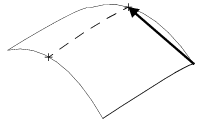
- Chordal: The direction of the offset vectors is defined by the surface point having
the specified distance from the considered curve point. The surface is selected in the field 'Support'.
- View: The curve will be offset in view direction.
- Plane: The curve will be offset in normal direction of the plane selected in the field 'Plane'.
- Support: Selection of a surface for the options 'Normal to Surface', 'On Surface' and 'Chordal'.
- Plane: Selection of a plane for the option 'Plane'.
- Alignment: Definition of the offset direction.
- Distance: Definition of the distance of the offset curve from the original curve (offset distance).
 Invert direction: The direction is inverted.
The Distance value is also inverted.
Invert direction: The direction is inverted.
The Distance value is also inverted.- Input field: Specification of a distance value. The input field is inactive if the check button 'Point' is switched on.
 Revert direction: Only the direction is inverted.
The Distance value remains unchanged. This allows, for example, to use positive values only.
- Point: If this option is activated, a point can be selected through which the offset curve shall pass.
The input field for the offset distance and the offset manipulators will be deactivated.
the selected point must correspond to the offset direction set in the field 'Alignment'. If, for example, the option 'On Surface' is set, the point must lie upon this surface.
If the option 'Both Sides' is additionally switched on, the two result curves are created with the distance defined by the point selection.
The option 'Individual' is inactive.
Definition of the offset distance by selecting a point

- Extrapolation: These options are only available for the Alignment modes Chordal and
On Surface.
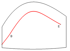
The result curve can be extrapolated by tangency at its Start and/or End up to the edges of the surface selected in the field 'Support'.
No extrapolation
('Start' and 'End' OFF)Extrapolation at the start
('Start' ON and 'End' OFF)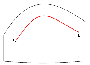
If G3 is used, the range of the curve will be extended to the support surface's limit, so that no additional segment will be inserted.
control point mesh before G3 extrapolation Control point mesh after G3 extrapolation 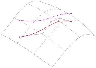
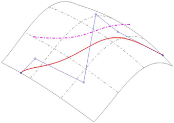
The number of
control points has
not changed. - Options:
- Both Sides: The curve offset is created both in positive and negative direction.
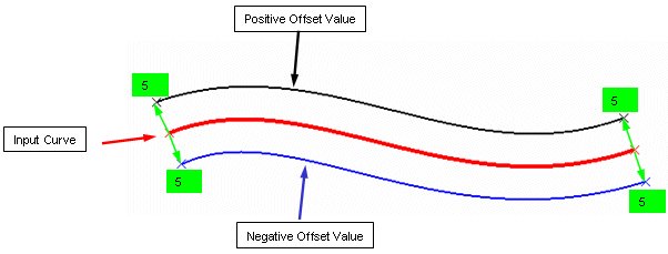
- Individual: If this option is switched on, each offset manipulator can be modified individually.
'Individual' OFF 
'Individual' ON 
- Trim: If this options is switched on, intersecting curves will be trimmed at the intersection point.
'Trim' OFF 'Trim' ON 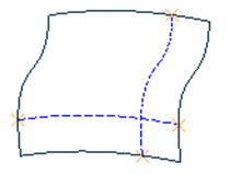
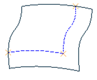
- 2D Curve: This option is only available for the Alignment modes Chordal and
On Surface.
The result is a 2D curve, according to the analysis with the command 'Geometric Information' in the Tools Toolbar also called Parameterized NURBS curve.
- Both Sides: The curve offset is created both in positive and negative direction.

- Display: The graphical display of the deviation values can be globally switched on and off.
- Dynamic, Static, None: See Apply Modes
- Deviation
- Curve: Displays the maximum deviation of the smoothed offset curve from the exactly computed curve points.
- Support: Displays the maximum deviation of the smoothed offset curve from the surface selected as support when using one of the options On Surface und Chordal.
- Output Result: See Output Result
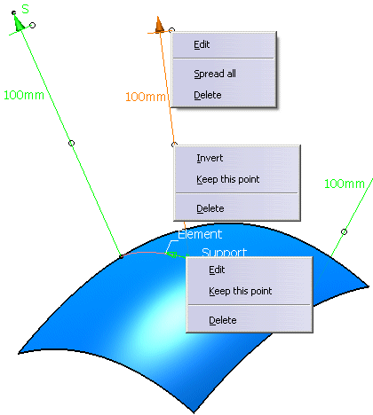
Contextual commands of the manipulators
The contextual commands will be activated by clicking the right mouse button on a vector or point manipulator handle. The following options can be defined:
- Edit:
- Vector contextual command: Changes the offset distance.
- Point contextual command (for individually inserted manipulators only): Changes the point position.
- Spread all: Assigns the current value to all other manipulators.
- Invert: Inverts the offset direction.
- Keep Point: Creates the point at the picked position.
- Delete (for individually inserted manipulators only): Deletes the manipulator.
![]()