 |
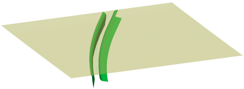
Open the CreateGap.CATPart document. |
 |
-
Click the Create Gap icon  . .
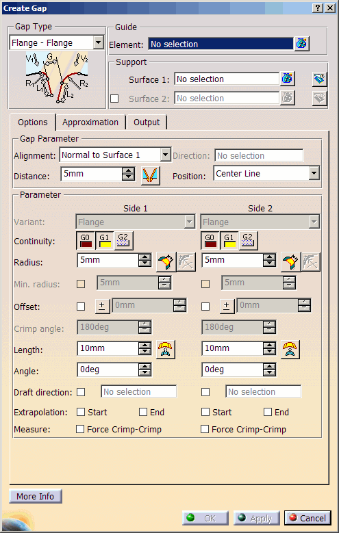
The Create Gap dialog box is displayed.
|
|
| |
-
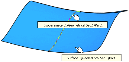
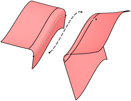
Select as Guide Isoparameter.1 and Surface.1 as Support.
|
 |
| |
-
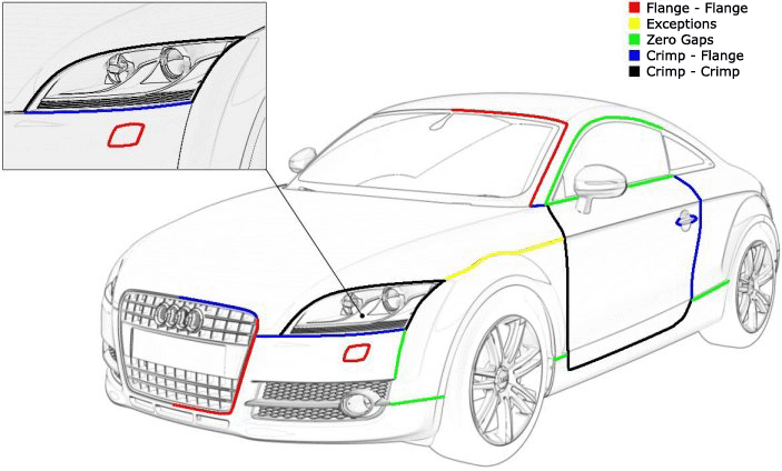
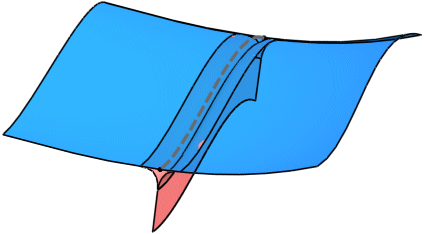
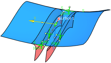
Select the Gap Type Flange - Flange and click Apply to create the gap.
|
 |
| |
-
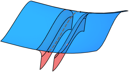
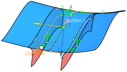
Use the Distance manipulator to increase the gap distance.
|
 |
| |
-
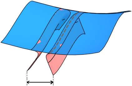
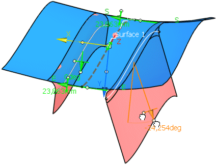
Use the Length and Angle manipulator to modify length and angle of the flange on Side 2.
|
 |
| |
-
Activate the option 'Trim Support'
 and create
the gap with OK. and create
the gap with OK.
|
 |
 |
You can define the following options:
|
| |
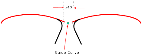
- Guide - Element: The Guide is used as driving curve for Gap type elements either on either side of the guide
curve.
The following element types can be selected as guide:
- surface edges (patch edges) – all Bezier, Nurbs, Splines, Nupbscurve, Pcurves
- Face Edges – Pcurves
- Curves (curve segments) – Only curves lying on the reference surface are allowed.
|
|
| |
- Support:
- Surface 1: Selection of the supporting surfaces on which the Gap type element shall be created.
- Surface 2: Selection of an alternative set of support surfaces. For example, the Surface 2 support surfaces
may be of a different shape and position to that of the surfaces used in Surface 1.
|
Surface 1

Surface 2

|
| |
Options tab |
|
| |
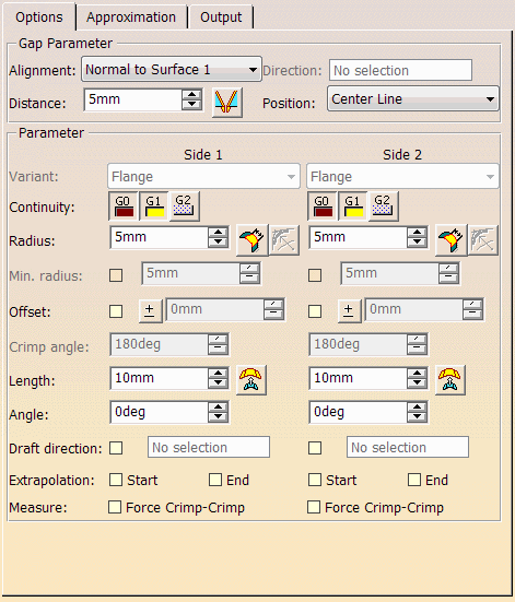
Gap Parameter
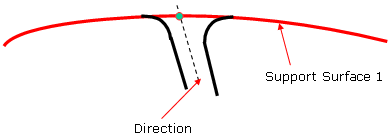
- Alignment:
- Normal to Surface 1 (default): The Gap feature draft angle is measured from the surface normals used in Surface
1.
- Direction: The Gap feature draft angle is calculated from a given direction selected or created by the user.
The direction field becomes active when this option is chosen.
|
Normal to Surface

Direction
|
| |
- Distance: Defines the distance between the resulting gap surfaces. The gap surfaces are
calculated depending on the Gap Type selected.
Parameter value is stored within the Feature Specification tree.
 Individual Distance at each manipulator:
The Gap distance can be individual at each manipulator. A new manipulator can be created by moving the contact point in the
middle of the Guide. Individual Distance at each manipulator:
The Gap distance can be individual at each manipulator. A new manipulator can be created by moving the contact point in the
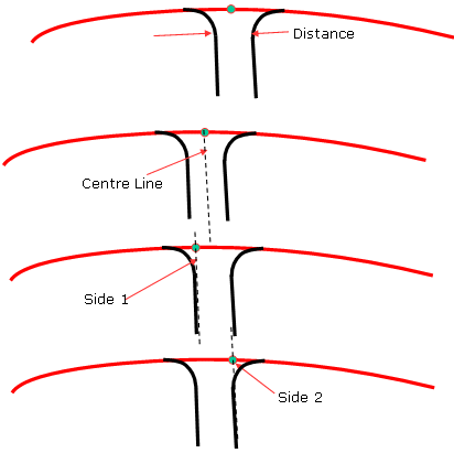
middle of the Guide.- Position: Defines the gap position relative to the guide curve. Three options are available:
- Center Line
- Side 1
- Side 2
|
|
| |
Parameter Side 1 / 2
- Variant: Only available for the gap types 'Crimp-Crimp' and 'Crimp-Flange'.
The Variant side options 1 & 2 allows the user to alter the Type of Fillet Flange result on one side according the Gap Type
selected. Certain options are only available according to the Gap Type:
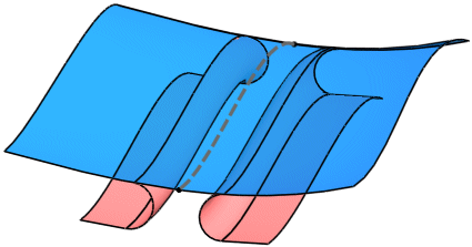
- Gap Type: Crimp - Crimp: Options available on each variant side: 'Crimp' and 'Crimp-Flange'.
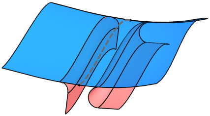
- Gap Type: Crimp - Flange: Options available on each variant side: 'Crimp', 'Crimp-Flange', and 'Flange'.
The following combinations are possible:
| Side 1 |
Side 2 |
| Crimp |
Flange |
| Crimp-Flange |
Flange |
| Flange |
Crimp |
| Flange |
Crimp-Flange |
|
Gap Type: Crimp - Crimp
Variant: Crimp - Crimp

Variant: Crimp - Crimp Flange

Variant: Crimp Flange - Crimp Flange

Gap Type: Crimp - Flange
Variant: Crimp - Flange

Variant: Crimp Flange- Flange

|
| |
- Continuity: For the gap type Crimp-Flange only available for the variant 'Flange'.
There are 3 continuity settings available to the user for the resultant Fillet of the feature:
- G0: No Fillet is created.
- G1: Tangency continuity is maintained between the Fillet and support surfaces.
- G2: Curvature continuity is maintained between the Fillet and the support surfaces.
|
 |
| |
- Radius: Definition of a radius value across the full length of the Fillet.
Parameter value is stored within the Feature Specification tree.
 Chordal: A fillet
with chordal parametrization is created. Chordal: A fillet
with chordal parametrization is created. True min.
Rad.: Minimum radius is controlled. Trace curves will be computed 1.5 x Mid Radius value for both G1 and G2. True min.
Rad.: Minimum radius is controlled. Trace curves will be computed 1.5 x Mid Radius value for both G1 and G2.
|
| |
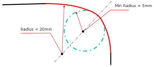
- Min. Radius: Only available for the variant 'Flange'.
Definition of a minimum radius across the full length of the fillet.
Parameter value is stored within the Feature Specification Tree.
|
|
| |
- Offset: Only available if the support surface is not trimmed. An offset is added between the support surface
and the side of the gap. Positive values define an offset on the side of the gap, negative values on the other side.
|
| |
- Crimp Angle - Side 1 & 2: Only available for the variants 'Crimp' and 'Crimp-Flange'.
Definition of the angle in which the Flange portion of the section is angled.
The angle must be greater than 180°.
If, in case the variant 'Crimp-Flange' is used, the angle is 360°, no flange length can be specified.
Parameter value is stored within the Feature Specification tree.
|

|
| |
- Length: Defines Flange length.
 Offset
distance : The flange ends at the specified distance from the support surface. Offset
distance : The flange ends at the specified distance from the support surface.- Angle: Defines the Flange angle.
- Draft Direction: For both sides only available for the variants 'Flange - Flange'. For the variants 'Crimp
-
Flange' and 'Zero Gap', the draft direction can only be specified for one side.
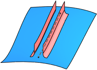
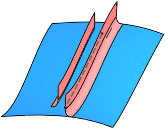
- Extrapolation: If the crimp surfaces have a smaller extent than the support, they can be extrapolated at the
start and/or end curves until the edges of the support.
 |
 |
| No Extrapolation |
Extrapolation Side 1 Start and End |
- Measure: Force Crimp - Crimp : Only available for 'Flange - Flange'. Forces the measure of the gap to use the
method of 'Crimp - Crimp' type even for 'Flange - Flange'.
Parameter values are stored within the Feature Specification tree.
|
| |
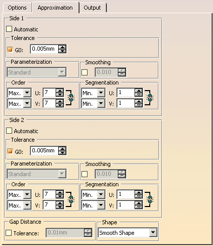
Approximation tab |
 |
| |
The approximation can be computed individually for each side if the link symbol are inactive. The
options are described on the page Approximation tab. In this tab, the following options are additionally
available:
- Gap Distance:
- Tolerance: The gap between each fillet is calculated to a given tolerance.
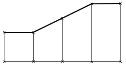
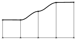
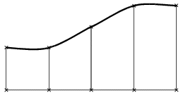
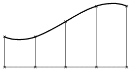
- Shape: Specifies the shape of the surface, i. e. the transition type between the individual selected profiles.
|
Linear Shape
|
Local Shape
|
|
Smooth Shape
|
Global Shape
|
The option 'Smooth' is not available.
|
| |
See Output tab |
| |
Click 'More Info' to display deviations and output results. |
 |
| |
- Display: Depending on the options selected, values are displayed in the graphics area.
- Deviation:
- Side 1/2: G0, G1, G2: Displays the maximum continuity deviation of the gap result for both sides as a result
of the approximation settings imposed.
- U+V: Display of the UV vectors of curves and surfaces.
- MFT: Display of the local coordinate system for the moving frame type.
- Dynamic, Static, None: See Apply Modes.
- Output Result: See Output Result
|
|

|
