|
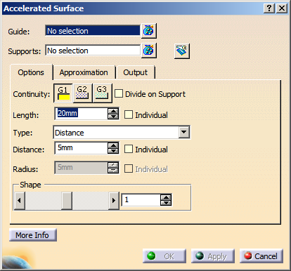
You can define the following options:
- Guide: Selects the guide.
Valid inputs are 3D curves and lines of type Bézier, NURBS, and B-Spline, as well as surface edges.
- Supports: Selects support elements.
Valid inputs are surfaces of type Bézier, NURBS, and B-Spline.
|
| |
 Trim Support:
Trims the support surfaces according to the contact edge. The side in which to keep is depicted by the X direction of the
manipulator. Trim Support:
Trims the support surfaces according to the contact edge. The side in which to keep is depicted by the X direction of the
manipulator.
If the guide curve is smaller than the support surface, automatic tangency extrapolation is performed of the trim boundary.
|
 |
|
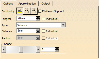
Options tab |
 |
| |
- Continuity: Specifies the continuity between created accelerated surface and support from G1 to G3.
- Divide on Support: In case of support surfaces consisting of multiple cells, the resulting accelerated surface
is divided at the cell boundaries in v-direction of the support surface.
|
| |
- Length: The length is the distance between the guide and the edge of the accelerated surface
lying on the support surface (edge 2 in the figure).
- Individual: Makes it possible to apply individual lengths at each end of the accelerated surface.
|
 |
| |
Type:
- Distance: Defines the accelerated surface by the Distance between the guide and
the edge of the accelerated surface lying normal to the support (edge 1).
- Individual: Allows to apply individual distances at each end of the accelerated
surface.
|
 |
| |
- Radius: Defines the accelerated surface by the curvature Radius at the edge of
the accelerated surface lying normal to the support surface (edge 2).
- Individual: Allows to apply individual radii at each end of the accelerated
surface.
|
 |
| |
- Shape: Modifies the tangent length of the result via the scroll bar or the text box.
A small value results in a flat and a big value in an embossed accelerated surface.
|
 |
| |
See Approximation tab |
| |
See Output tab |
| |
Click 'More Info' to display deviations and output results. |
 |
| |
- Display: Depending on the options selected, values are displayed in the graphics area.
- Deviation:
- G0, G1, G2, G3: Display of the maximum continuity deviation condition along the accelerated surface edge
lying on the support surface.
- U+V: Display of the UV vectors of curves and surfaces.
- MFT: Display of the local coordinate system for the moving frame type.
|
 |
| |
|
 .
.