Open the
Constraint1.CATPart document.
Make sure the Constraints option is selected in
Tools > Options > Infrastructure > Part Infrastructure > Display
tab, so that you are able to see the constraints in the specification tree.
-
Click Matching Constraint
 in the FreeStyle Constraints toolbar.
The Match Constraint dialog box displays. The continuity constraint created appears in the specification tree under the Free Form Constraint.X as given below.
In the Match Constraint dialog box you can:
- Elements: Manages elements involved in the continuity
constraint:
- Source: The element to be deformed; an edge for surface matching, a vertex for curve matching. The element such a surface or a curve selected before the command is taken as an input for Source element.
- Target: The reference elements; You
can select one or two edges of a surface or curves having G1
continuous connection between them. At least one target must be
selected.
Note: You can automatically select the possible target element after choosing the source element. For more information, refer to Automatic target selection. Use the Only current body option if you want to select a target edge of the current visible body only. -
 Swap: Swaps the source and target elements.
This option is unavailable if two targets
elements are selected.
Swap: Swaps the source and target elements.
This option is unavailable if two targets
elements are selected.
- Limits: You can create
the points to define the limit area on the target edge using the
contextual commands available from the boxes in the Limits area. These points can be
outside the target curve. In this case, the constraint computes the
minimum distance between the target curve and point, and uses the
corresponding position on the target curve for limit.
-
 Partly: The matching surface meets the edge of the reference surface
partly, manipulators appear to move the two meeting points. The two
boxes are available where you can specify the limiting points.
Partly: The matching surface meets the edge of the reference surface
partly, manipulators appear to move the two meeting points. The two
boxes are available where you can specify the limiting points.
-
- Options:
-
 Inside: Projects the boundary on the target surface.
Displays the position where the edge will reach
on the target surfaces as a result of matching.
Inside: Projects the boundary on the target surface.
Displays the position where the edge will reach
on the target surfaces as a result of matching.
This option is only available if Exact is not selected. If this option is selected, Exact options are grayed out.This option is automatically unselected if an edge is selected as the target element while creating a matching constraint. -
 On basic geometry:
Matches curves or surfaces with the underlying geometry i.e.
considering the trimmed elements.
On basic geometry:
Matches curves or surfaces with the underlying geometry i.e.
considering the trimmed elements.
With On basic geometry option ON 
With On basic geometry option OFF -
 Diffusion: Modifies a maximum of ranks of control points in the element
to be deformed, otherwise only the first rank is modified.
Diffusion: Modifies a maximum of ranks of control points in the element
to be deformed, otherwise only the first rank is modified. -
 Adapt: Adapts the transversal order of the surface to be matched with
the transversal order of the target surface.
Adapt: Adapts the transversal order of the surface to be matched with
the transversal order of the target surface.
This option is available only of the target edge is an isoparametric of its support surface. -
 Display deformation distance: Displays the maximum deviation
value and its position between the original surface and the modified
surface in the graphic area. The original mesh before the
modification is also displayed.
Display deformation distance: Displays the maximum deviation
value and its position between the original surface and the modified
surface in the graphic area. The original mesh before the
modification is also displayed.
While using the command you can reset the reference. Right-click the arrow of the variant display and select Reset Delta Reference to reset the reference.The existing position of the surface is set as new reference. The reference mesh and the maximum deformation distance are computed with respect to the new reference. -
 Auto Apply: Performs the deformation of the surface to be matched each
time you modify an option.
Auto Apply: Performs the deformation of the surface to be matched each
time you modify an option. -
 No Highlight Representations:
Deactivates the highlight on the selected elements to avoid
conflicts with the display of other entities such as control points.
No Highlight Representations:
Deactivates the highlight on the selected elements to avoid
conflicts with the display of other entities such as control points. - Continuities: There are two types of algorithm that can be used
together; the exact algorithm and the approximated algorithm.
If both of them are used, the first one to be performed is the exact one, then the approximated.- Exact: The first rank of control points of the element
to be deformed takes a regular distribution according to the target
element. Other ranks keep their distribution.
Available orders of continuity for this algorithm are:-
 /
/ G0 (selected/cleared)
 -
 /
/ G1 (selected/cleared)
 -
 /
/ G2 (selected/cleared)
-
- Exact: The first rank of control points of the element
to be deformed takes a regular distribution according to the target
element. Other ranks keep their distribution.
- Approximated: The distribution of the first rank of
control points of the surface to be deformed is kept as is.
Other ranks keep their distribution.
Available orders of continuity for this algorithm are:-
/
G0 (selected/cleared)
-
/
G1 (selected/cleared), only for the start and the end of
the edge.
-
/
G2 (selected/cleared) only for the start and the end of
the edge.
-
 The position of the start and end transversal boundaries is
blocked. The value of the continuities on these edges does not
impact the position of the boundaries.
The position of the start and end transversal boundaries is
blocked. The value of the continuities on these edges does not
impact the position of the boundaries. -
 /
/ unlink/link orders of continuity for the start and the end of the edge.
-
- Opposite: You can change the
continuity values to be kept at the opposite edges either via the
context menu at the continuity labels in the work area or by these
options in the dialog box. The values are automatically updated in the
respective environment.
-
 Free
Free
-
G0
-
G1
-
G2
-
- Opposite Continuities:
Source Opposite:

These options are available only if the Diffusion
option is selected.
Defines continuities to be kept at the opposite curve end or surface edge of the source.
When using the Diffusion
option, control point/row modifications done to
achieve the continuity with the target is propagated to
other control points/rows than the ones directly involved by
the specified continuity. This may move control points/rows
at the opposite end or edge and thus modify the continuity
at the opposite end or edge.
At the opposite end point of the source curve or at the surface edge, you can specify a maximum continuity to be kept using either the Max. list in the dialog box or using the context menu available at the continuity labels which appear when the Diffusion
option is selected.
G0 continuity is set by default, but you can select any other continuity irrespective of whether the order allows to keep it or not. If the continuity cannot be kept, the maximum possible continuity is applied and displayed under Applied in the dialog box marked by asterisks in the context menu.
The Free option applies no continuity. This allows the movement of all control points or control point rows, without keeping any continuity, to obtain an optimal control point distribution with the Diffusion
option. As in this case no continuity is kept at
opposite, the continuity with neighboring elements at the
opposite end point or edge may be broken.
- Matching constraints between source and target always have priority over the continuity specified at the opposite in case that both continuities cannot be kept.
- Create another matching constraint between the opposite end point or edge and the other target to manage the wanted continuity at the opposite with the same priority.
See, Mean Surface Solver. - Support: Defines the
direction in which the
control points is projected.
Along direction: If this option is cleared the movement is along the local normal of the target element.
If this option is selected the movement of control points depends on the propagation mode selected. The following modes are available which define the projection direction:
Along View: The direction is along the view direction. The control points move along the depth of the viewpoint. To see the control point movement rotate the part.
User Line/Plane: The direction is along the selected line or normal to the selected plane. The Compass option is available
only with this mode. Right-click the compass selection field and
select the axis or plane. Using the contextual menu you can create
the required element. If Compass
is ON, you can set this direction by manipulating the compass in 3D.
option is available
only with this mode. Right-click the compass selection field and
select the axis or plane. Using the contextual menu you can create
the required element. If Compass
is ON, you can set this direction by manipulating the compass in 3D.
Along Source: The control points for G1/G2 are projected along the normal of the source. In case Inside mode is selected, the edge of the surface to be modified (the G0 row) is projected orthogonally on the target surface. - Modification Ratio:
Move the slider to specify a ratio for displaying an intermediate
result between the original and last applied status. It helps to
control the final result with the best possible solution between all
the constraints modifying the particular surface.
Minimum and maximum values in the Deviation section are updated dynamically with the modification ratio.
Once you exit the Matching Constraint command with certain modification ratio, the next update of the constraint ignores the earlier specified ratio. - Deviations: Displays the deviations according the orders
of continuity.
Select and
and
 to display the minimum and maximum deviation respectively.
By default, minimum deviation
is not selected and the maximum
deviation
option is selected.
Some of the options such as Gap Options, G3, Alignment, and Both are available only with the licenses containing ICEM.
For more information, see ICEM Shape Design User's Guide: Basic Tasks: Shape Modification: Creating a Matching Constraint. - Elements: Manages elements involved in the continuity
constraint:
-
Move the pointer to the edge of the source surface to be matched and click when it is highlighted in red dashes.
The source surface is highlighted in blue. 
-
Move the pointer onto the target surface and click when the reference edge is highlighted in red dashes.
The target element is highlighted in red. If one of the Both options is selected, the source and target surfaces will be highlighted in blue. 
-
Click the surface when the adequate boundary is highlighted.
As the Partly option is selected, two green manipulators represent the projection of the source element onto the target element.
These manipulators can be moved along the edge. -
Click Apply.
The surface is modified according to the options. 
-
Clear the
Partly option and click Apply again.The surface is modified on all the edge. 
Right-click the continuity type to display the contextual menu, you are able to: - Modify the chosen type: Point continuity (G0), Tangent continuity (G1),Curvature continuity (G2) or G3 continuity (G3).
- Activate/Deactivate: Activates/deactivates the constraint.
- Update Network: Updates the constraints linked ones with the others, from the selected constraint and while taking into account their creation order.
- Apply Constraint: Updates locally the constraint.
- Delete: Deletes the constraint.
-
Click OK in the Match Constraint dialog box.

Click OK button does not perform the Apply operation. -
Create several constraints like these.
-
Right-click the G0 (tangent) continuity as shown and change the continuity type to G2 (curvature).
-
Click the G2 (Curvature) continuity arrow to reverse the direction of the constraint.
-
Right-click a G0 continuity and deactivate it.
Color of the continuity indicates its activating status: - Red, activated.
- Red-yellow, deactivated.
-
Select the Surface.2 and click Control Points
 in Shape Modification toolbar
to display the control points and mesh lines on the surface, allowing you
to dynamically modify them.
in Shape Modification toolbar
to display the control points and mesh lines on the surface, allowing you
to dynamically modify them.The source surface deforms so that the neighboring constraints are automatically updated.
Note that the deactivated constraint is not taken into account.
- You can create as many constraints as there are elements.
- You can deactivate the constraints using the Deactivate contextual menu.
- Constraints created using this command are very similar to the constraints created in the Part Design and the Sketcher workbenches: they are compatible and are solved using a variational approach.
-
Click Cancel in the Control Points dialog box.
-
Select the Surface.2 and click In Model or on Perch
 in the Quick Compass Orientation toolbar,
to switch the compass from the perch to the selected surface, see
Managing the Compass.
in the Quick Compass Orientation toolbar,
to switch the compass from the perch to the selected surface, see
Managing the Compass. -
Use the compass to move the surface.
All the constraints are updated accordingly, except the deactivated constraint. 
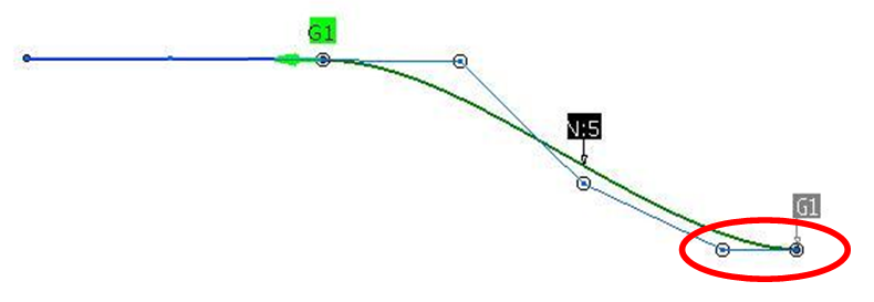
- You can apply the continuity
constraint on the opposite vertex of the selected source curve while
matching the two curves. Use the Diffusion
option to move the control points except those defining this
continuity on the opposite edge. For example, if the continuity of
the opposite edge is G1, the last two control points of the selected
source curve will be fixed.
Note: You can see the continuity tags at the opposite vertex of the constraint by clicking Continuity  on the Generic Tools toolbar.
 - You can define the continuity constraint on the opposite edge of
the selected edge. You can apply Free continuity (F), Point continuity (G0),
Tangent continuity (G1), Curvature continuity (G2)
or G3 continuity (G3) by right-clicking the
default constraint and selecting the appropriate continuity
constraint. The row of the control points are fixed to
ensure the selected continuity on the opposite edge.
E.g. if the continuity of the opposite edge is G1, the last 2 rows of control point will be fixed.
In case the order of the Source surface is not sufficient to compute the continuity on the both edge (primary and its opposite edge), the constraint is applied only to the primary edge. - If you want to delete a constraint, delete it in the specification tree, under the Free Form Constraint.X node. However, it is also possible to delete the constraint using the contextual menu or in the 3D, by selecting the constraint and hit Delete key.
- You can get the result of multiple constraints surface is a mean surface between each constraint result by selecting Mean Surface Solver option in Tools > Options > Shape > FreeStyle > General tab, Matching Constraint command options area. If a surface is modified by two constraints, the results for the two constraints are computed separately. The final result is a mean surface between those two intermediate results.
- If several constraints are linked together and either the target
or source element of a constraint is modified, then all the linked
constraints are updated. The constraint taking the modified
element as its input is updated last. This is to ensure that the
continuity is maintained on the modified element.
After the update process, the continuity created by the constraint that is not the last one to be updated may not be met. In such a case use the Apply Constraint contextual menu on the constraint. - You can insert a constraint set on the existing constraint set by right-clicking Free Form Constraint.x root node in the specification tree using the Insert Constraint Set contextual menu.
- You can also insert a constraint set on the existing constraint set in Insert > Free Form Constraint Set.... In the Insert Constraint Set dialog box, type the name of the constraint set in the Name box. Select the father of the constraint set in the Father list or by selecting the constraint from the specification tree. Select the children of the newly created constraint set from the specification tree.
Open the
Constraint2.CATPart document.
Select Mean Surface Solver option in Tools > Options >
Shape > FreeStyle > General tab,
Matching Constraint command options
area.
|
Constraints can only be set on datum elements.