 |
| This page deals with the options concerning:
|
Geometry
|
| Defines the geometry options: |
Tolerances
|
| Defines the user-defined tolerances to every element to be created and
modified within a FreeStyle workbench or the Automotive
Class A workbench. |
Constraint
|
Defines the continuity variation. In this case if the continuity is
over the set value the element is not created/modified.
This value cannot be modified in P1-mode. |
 By default, the value is 0.1.
 |
Deviation
|
| Defines the deviation tolerance value used when converting elements
using the Converter Wizard for example (see tasks
Approximating/Segmenting Procedural Curves and
Approximating/Segmenting Procedural Surfaces within the
FreeStyle Shaper, Optimizer, and Profiler User's Guide). In this
case you accept the conversion up to the set tolerance value. |
 By default, the value is 0.1.
 |
Order
|
Defines the maximum allowed order along the U (and V) directions for
each curve segment and surface patch. This maximum order value ranges from
5 to 16 included, in a given direction.
This value cannot be modified in P1-mode. |
 By default, the value is 16.
 |
 |
Auto Detection
|
| Defines the auto detection options: |
Coordinates
|
| Defines whether the point coordinates are displayed as the pointer
moves along the geometry. |
 By default, this option is not selected.
 |
Search Dressing
|
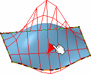
| Defines whether the control points on geometry detected with the
pointer are displayed when using the Snap on Cpt (snap on
control points) option from the Dashboard. |
 |
 By default, this option is selected.
 |
 |
Display
|
| Defines the display options: |
Control Points
|
| Defines whether the control points are displayed on the geometry. See
Displaying Control Points Temporarily in the FreeStyle
Shaper, Optimizer, and Profiler User's Guide). |
 By default, this option is not selected.
 |
Continuity
|
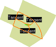
| Defines whether the continuities are displayed at every connection
between elements (such as blend and match curves and surfaces, fill
surfaces, and so forth). |
 |
 By default, this option is selected.
 |
Curvature
|
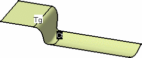
| Defines whether the curvature texts are displayed on an element (such
as blend and match curves and surfaces, and so forth). |
 |
 By default, this option is not selected.
 |
Order
|
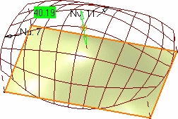
| Defines whether the order number is displayed along the U (for curves)
or U and V directions (for surfaces). |
 |
 By default, this option is selected.
 |
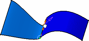
Contact Point
|
| Defines whether the contact point is displayed at every connection
between connected elements (such as blend and match curves and surfaces,
and so forth). |
 |
 By default, this option is selected.
 |
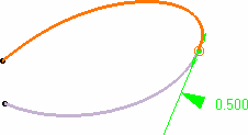
Tension
|
Defines whether the tension manipulators are displayed oat every
connection between connecting elements (such as blend and match curves and
surfaces, and so forth).
This option is P2-only. |
 |
 By default, this option is not selected.
 |
 |
Tuning
|
| Defines the tuning options, these options are P2-only.
|
|
|
Coefficient
|
| Defines the coefficient value used when manipulating views or geometry. |
 By default, the value is 0.2.
 |
 |
- The coefficient values can be set between 0.00001mm
and 1mm.
- If the coefficient value entered is less than or
equal to 0.00001 it will use the default value 0.2mm.
- If the coefficient value entered is greater than 1mm
it will take default value 1mm.
|
|
|
Rotation Step
|
| Defines the rotation step value used when manipulating views or
geometry. |
 By default, the value is 1.000.
 |
 |
Selection options
|
| Defines the selection focus options. |
Full Cross
|
| Defines whether a full cross is displayed. |
 By default, this option is not selected.
 |
All Mesh
|
| Defines whether all the mesh is selected when editing control
points. |
 By default, this option is not selected.
 |
Filter options :
deselect all points
|
| Defines whether all the selected control points of the selected
elements are deselected when the Filters mode is changed in
the Control Points dialog box. |
 By default, this option is not selected.
 |
 |
Matching
Constraint command options
|
| Defines the matching constraint options. |
Default activation status
|
| Defines the constraints created during the Matching Constraint
command to be deactivated. When the constraint is deactivated, it is not
updated when its inputs (source or target) is modified outside the
Matching Constraint command. |
Minimum Corner Distance
|
| Defines the relimitation manipulator that is used to move the
constraint to snap directly at to the corner of the selected face when
it gets closer than the value defined. |
Mean Surface Solver
|
| Defines the result between multiple constraints surface as a
mean surface between each constraint result. If a surface is modified by
two constraints, the results for the two constraints are computed
separately. The final result is a mean surface between those two
intermediate results. |
Automatic target selection
|
Defines the distance around the source element for automatic target
selection when using the Matching
Constraint command. Use the
Automatic target selection
 option
to apply this setting. option
to apply this setting. |
 By default, this option is selected and the value is set to 10mm.
 |
 |
Mirror Analysis option
|
| Defines the mirror display options during Mirror Analysis command. |
Feedback color
|
Defines the default color in which the mirrored elements and
analysis are displayed when
Display mirror tags
 is
active in the Mirror Analysis dialog box. is
active in the Mirror Analysis dialog box. |
Parallel Command
|
| Warn when cancelling the Parallel Command Session |
|
Displays a warning message when cancelling a parallel command session. |
  By default, this option is cleared.
 |
| Enable insertion of current running command into a
Parallel Command Session |
|
Inserts a current running command into a parallel command session in
parallel with another command by launching the latter, which is able to run in parallel. |
  By default, this option is cleared.
 |
Mapping Analysis option
|
| Defines the material display options during
isophote mapping
analysis command. |
No warning message if material mode is not ON
|
| Select this check box if you want the material mode to be
automatically ON during the isophotes mapping analysis even though the
Materials option in the View > Render Style > Customize
View command is cleared. No warning message is displayed. |
 |
Soft Mirror
|
Define the symmetry plane for mirror operation.
The following options are available:
- XY Plane
- YZ Plane
- ZX Plane
- User Defined Plane.
|
|
 By default, ZX Plane is selected.
 |
 |
Curve Analysis Result
|
|
Select the check box if you want to keep the
intersection curves as NURBs. If you clear the check box the intersection
curves are kept as parameterized curve. |
 By default, this option is not selected.
 |
 |
Control Points Border 3D Curve Mode
|
|
Select the check box to create a separate 3D NURBs curve from a surface
edge which is selected as an input element for the
Control Points command. |
 By default, this option is cleared.
 |


