This task shows you how to create a surface mesh using rules and parameters that are defined in a mesh rule file.
- Open the Sample06.CATAnalysis document from the samples directory.
- The Rule Based Meshing (RBM) product must be installed.
- At least one mesh rule file must exist. See Creating and Modifying Rules.
-
Click Rule Based Surface Mesh
 in the Rule Based Surface Method toolbar.
 -
Select the geometry to be meshed.
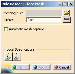
The Rule Based Surface Mesh dialog box appears.
-
Click
 , select the mesh rule file (.CATFmtRules) you want to use,
and click OK.
, select the mesh rule file (.CATFmtRules) you want to use,
and click OK.If no mesh rule file is created, you have to create a mesh rule file. See Creating and Modifying Rules. -
To visualize the rules defined in the selected file, right-click the file name in the Meshing rules box, and select View.
The Meshing Rules Editor dialog box displays the rules that define mesh parameters, geometry parameters, mesh quality criteria, and geometric features. You cannot modify the parameters defined in the dialog box. To learn more about this dialog box and how to modify rules and parameters, see Creating and Modifying Rules. -
To offset the surface mesh from the selected geometry, enter a value in the Offset box.
If the selected geometry includes thickness properties, they are used to create the offset. You cannot edit the offset value in this case. An arrow indicates the offset direction on the selected geometry. An offset in RBM is based on a simplified representation of the surface positioned at the offset location. The geometry is not changed by the offset process, and changes to the offset surface mesh are associative with changes to the underlying geometry.
-
To capture nodes and edges of elements from the neighbor meshes in order to obtain a compatible mesh:
-
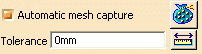
Select the Automatic mesh capture check box.
-
Click
 to
specify the mesh parts that contain the mesh to be captured
according to a tolerance value.
to
specify the mesh parts that contain the mesh to be captured
according to a tolerance value.
- Only meshes of updated mesh parts can be captured.
- You cannot select mesh parts that belong to another .CATAnalysis document.
-
In the Tolerance box, enter a maximum distance to capture nodes and edges of elements of the selected mesh parts.
-
Select the Automatic curve capture check box to automatically project curves from nearby features.
The curve projection tolerance is the same as the mesh capture tolerance specified above.
The mesh capture is performed using the condensation mode; that is to say that the nodes of the captured mesh and the surface rule mesh are shared, they are not duplicated. The mesh capture is performed dynamically on all the constraints (free edges, internal edges...) and after all constraints modifications.
-
-
To project external curves independent of the mesh capture process and use the result of this projection to constrain the topology of the mesh:
-
Click Project Curves
 .
.The External Curve Constraint dialog box appears. -
Select the curves you want to constrain.
-
In the Tolerance box, enter a maximum distance to project external curves.
If the distance between an external curve and the mesh is greater than the tolerance value, the curve is not projected. -
Click OK.
A Geometry Specifications set containing a Projected Curve local specification appears in the specification tree under the mesh part.
-
-
To project external points and use the result of this projection to constrain the topology of the mesh:
-
Click Project Points
 .
.The External Point Constraint dialog box appears. -
Select the points you want to constrain.
-
In the Tolerance box, enter a maximum distance to project external points.
If the distance between an external point and the mesh is greater than the tolerance value, the point is not projected. -
Click OK.
A Geometry Specifications set containing a Projected Point local specification appears in the specification tree under the mesh part.
-
-
Click one of the following:
- Cancel to cancel the mesh part creation and close the dialog box.
- Apply to create, update, and generate the mesh based on the rule file you selected.
- OK to create the mesh and close the dialog box.
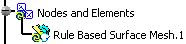
If you clicked Apply or OK, a Rule Based Surface Mesh.1 mesh part appears in the specification tree.
To modify an existing rule based surface mesh part, you must enter the Rule Based Surface Mesh editor. To learn more, see Using the Rule Based Surface Mesh Editor.