This task shows you how to create a mesh rule file and to modify an existing mesh rule file. A mesh rule file (.CATFmtRules) contains a set of rules that define mesh specifications, topologic specifications, quality criteria, and rules for geometric features such as holes, fillets, and beads.
- Open the Sample06.CATAnalysis document from the samples directory.
- The Rule Based Meshing (RBM) product must be installed.
-
Click Rule File Editor
 in the Rule Based Surface Method toolbar.
The Meshing Rules Editor dialog box appears and contains four tabs to define rules for the following parameters:
- Mesh to define the shape and type of elements you want to use to mesh the surface part.
- Geometry to define rules for topology simplification.
- Quality to define quality criteria that will determine the mesh quality.
- Feature to define rules for geometric holes, fillets, and beads.
-
To visualize or modify an existing rule file, click
 ,
and select the mesh rule file.
,
and select the mesh rule file.The dialog box is updated and displays the parameters corresponding to the selected mesh rule file.
-
To define rules for mesh parameters, select the Mesh tab.
-
In the Shape list, select one of the following options:
- Trias Only to mesh the surface with triangle elements exclusively.
- Quads Dominant to mesh the surface with quadrangle elements when it is possible, and allow triangle elements in transition regions.
- Quads only to mesh the surface with quadrangle elements exclusively.
-
In the Element type list, select Linear or Parabolic.
-
In the Mesh size box, enter a value for the global size of the mesh. The specified mesh size will be applied by the mesher wherever possible.
-
In the Minimum size box, enter a value to fix the minimum mesh size that you want to use.
-
In the Maximum size box, enter a value to fix the maximum mesh size that you want to use.
-
If you selected Trias Only, you can specify absolute and proportional sag specifications.
The absolute sag is the maximum gap between the mesh and the geometry. The proportional sag is the ratio between the local absolute sag and the length of the local mesh edge. 
Proportional sag value= (local Absolute sag value) / (local mesh edge length value)
You can use both absolute sag and proportional sag, the most constraining of the two values is used.
-
-
To define rules for geometry parameters, select the Geometry tab.
-
In the Angle between faces box, enter a value that specifies the minimum angle between faces to constrain the common edge (the angle is computed between the normals of the neighboring faces). If the angle between two faces is less than the specified value, those faces will be grouped.
-
In the Angle between curves box, enter a value that specifies the minimum angle between curves to constrain the common vertex.
-
In the Curvature angle box, enter a value that specifies the minimum angle to consider curved surfaces.
-
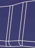
To merge edges during the topology simplification, select the Simplify geometry under check box, and enter a value to specify the minimum size of topological edges.
Whenever possible, edges are merged if the topological edges are smaller than the specified value or if the distance between two edges is less than the specified value. Consider the following geometry:
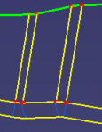
Result of the topology simplification when the Simplify geometry under check box is cleared:
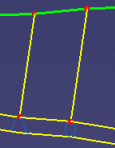
Result of the topology simplification when the Simplify geometry under check box is selected:
-
To ignore internal cracks, select the Ignore internal cracks check box.
-
-
To define rules for mesh quality parameters, select the Quality tab.
You can specify the following quality criteria to analyze the mesh quality: - Length
- Angle tria
- Angle quad
- Warp angle
To learn more about the quality criteria, see Analyzing Mesh Quality.
-
To define one or several rules for geometric features (holes, fillets, and beads), select the Features tab, and select the Recognize hole, Recognize fillet, or Recognize bead check box in the corresponding Holes, Fillets, or Beads tab.
-
To add a rule for geometric features, select the corresponding tab, right-click in the list, select Add Specifications, and choose one of the following:
- Remove Hole to ignore holes in the meshing process. See Remove Holes.
- Mesh around Hole to impose nodes by distributing them around a hole. See Mesh around Holes.
- N-layers Mesh to impose a number of layers to
mesh fillets. See Mesh Fillets.

If the Simplify geometry under check box is selected in the Geometry tab, fillets with a width less than the value specified in the Geometry tab are simplified, and the rule you define is ignored. - Remove Bead to ignore beads in the meshing process. See Remove Beads.
- Bead Mesh to impose a number of layers to mesh beads. See Mesh Beads.
The list in the corresponding tab displays a summary of the rules you have defined. Each cell of the list can be modified by clicking it.
Example of the Holes tab:
In this example:
- All the holes in the geometry with a diameter greater than 0mm (Min diameter) and less than 4.99mm (Max diameter) will be ignored by the meshing process.
- All the holes in the geometry with a diameter between 5mm and 9.99mm will be meshed, at least five edges will be created, with three layers. The height of the third layer will be automatically set by the meshing algorithm.
- All the holes in the geometry with a diameter between 10mm and 30mm will be meshed, at least ten edges will be created, with two layers. The height of the first layer will be automatically set by the meshing algorithm.
-
To delete a rule for a geometric feature, right-click the rule, and select Delete.
-
To modify a rule for a geometric feature, right-click the rule, and select Edit.
The corresponding dialog box appears. -
To check that the rules you defined for a geometric feature are consistent, click Check.
If some rules are in conflict, a message is displayed. A symbol also appears in the rule list to help you identify the rules in conflict.
Consider the following example:
The rule No.0 is in conflict with the rule No.1 because the Max diameter of the rule No.0 is greater than the Min diameter of the rule No.1.
This check is automatically done when you click Save Meshing Rules or OK.
-
To ignore rules defined for a geometric feature (hole, fillet, and bead), select the Features tab, and clear the Recognize check box in the corresponding Holes, Fillets, or Beads tab.
-
To save the parameters you have defined, click Save Meshing Rules.
The Save As dialog box appears:
-
Select an existing mesh rule file to overwrite it, or enter a name in the File name box to create a new mesh rule file.
-
Click Save.
-
-
Click OK.
 Remove Holes
You can specify holes in the geometry that you want to be ignored by the meshing process. Rules for holes are not applied to holes cut by a vertex.
-
Define the holes you want to be affected by the rule.
-
To specify a minimum diameter, select the Minimum diameter check box, and enter a value.
Holes with a diameter less than the imposed minimum diameter will not be affected by the rule. -
To specify a maximum diameter, select the Maximum diameter check box, and enter a value.
Holes with a diameter greater than the imposed maximum diameter will not be affected by the rule.
If you clear a check box, no threshold value will be imposed for the corresponding parameter.
-
-
Click OK in the Remove Hole dialog box.
All the holes with a diameter between the minimum diameter and the maximum diameter will be ignored by the meshing process. The list in the Holes tab displays a summary of the rule you have defined.
In this example, all the holes in the geometry with a diameter less than 0.5mm (Max diameter) will be ignored by the meshing process. There is no threshold value for the Min diameter (--- symbol).
Mesh around Holes
You can define the holes on which you want to apply a rule by entering a value for minimum and maximum diameters. Rules for holes are not applied to holes cut by a vertex.
-
Define the holes you want to be affected by the rule.
-
To specify a minimum diameter, select the Minimum diameter check box, and enter a value.
-
To specify a maximum diameter, select the Maximum diameter check box, and enter a value.
If you clear a check box, no threshold value will be imposed for the corresponding parameter.
-
-
In the Min number of edges box, enter the minimum number of edges you want to create on holes affected by the rule.
-
In the Layers list, select the number of layers you want to use to mesh around the holes affected by the rule.
-
To specify the height of a layer, select the corresponding check box, and enter a value. If you clear the check box for a layer, a value that is automatically computed by the rule based mesh algorithm is set.
-
Click OK in the Mesh around Hole dialog box.
The list in the Holes tab displays a summary of the rule you have defined: 
In this example, holes with a diameter between 9mm and 14mm will be meshed, at least five edges will be created, with three layers. The height of the third layer will be automatically set by the meshing algorithm.
Mesh Fillets
You can impose a number of layers to mesh fillets.
-
Define the fillets you want to be affected by the rule.
-
To specify a minimum width, select the Minimum width check box, and enter a value.
-
To specify a maximum width, select the Maximum width check box, and enter a value.
-
To specify a minimum angle, select the Minimum angle check box, and enter a value.
-
To specify a maximum angle, select the Maximum angle check box, and enter a value.
If you clear a check box, no threshold value will be imposed for the corresponding parameter.
-
-
In the Layers list, select the number of layers you want to use to mesh the fillets affected by the rule.
You can mesh fillets using one, two, or three layers.
Consider the following fillet (highlighted in orange):
Result of a mesh with two layers:
Result of a mesh with three layers:
-
Click OK in the N-layers Mesh dialog box.
Remove Beads
You can specify beads in the geometry that you want to be ignored by the meshing process.
-
Define the beads you want to be ignored by the meshing process.
-
To specify a minimum width, select the Minimum width check box, and enter a value.
-
To specify a maximum width, select the Maximum width check box, and enter a value.
-
To specify a minimum height, select the Minimum height check box, and enter a value.
-
To specify a maximum height, select the Maximum height check box, and enter a value.
If you clear a check box, no threshold value will be imposed for the corresponding parameter.
-
-
Click OK in the Remove Bead dialog box.
Mesh Beads
You can impose a number of layers to mesh beads.
-
Define the beads you want to be affected by the rule.
-
To specify a minimum width, select the Minimum width check box, and enter a value.
-
To specify a maximum width, select the Maximum width check box, and enter a value.
-
To specify a minimum height, select the Minimum height check box, and enter a value.
-
To specify a maximum height, select the Maximum height check box, and enter a value.
If you clear a check box, no threshold value will be imposed for the corresponding parameter.
-
-
In the Layers list, select the number of layers you want to use to mesh the beads affected by the rule.
You can mesh beads using two or three layers. -
Click OK in the Bead Mesh dialog box.