Datum Elements and Datum Systems
The toleranced feature is positioned relatively with the tolerance zone, and this set is positioned relatively with the datum or the datum system. These related positions will be specified using basic dimensions and they are displayed or not.
For more information about datum constitution and specification, see ISO 5459, ASME Y15.5M and ISO 1101.
Datum System Composition
Datum writing rules
When the datum triangle is placed on the outline of the element or on its extension line, the datum element represents the surface itself or the 2D representation of the surface, which is a line.
When the datum triangle is placed in the alignment of the dimension line, the datum element represents the median element (usually an axis or a median plane).
When the datum triangle points directly on a median element, the datum element represents either the median element itself (usually an axis or a median plane) or the resulting median element of the collection of the considered elements.
Datum Creation
When a datum is created from a pattern of features, a label Nx appears to right side of the datum, where N is the number of features the pattern is made of. The label:
|
Projected Extension Datum Modifier
The Projected extension area is available in the Datum feature dialog box when the datum feature is any of the following:
|
At a given time, only one of Projected extension option or Contacting Feature [CF] option is available for selection. Click any of the option to enable it. The other option is automatically disabled. Clicking the selected option again clears the selection and makes both the options available for selection.
Note: The selection field in the Projected extension area is available for creation or edition of extended cylinders. If the selected datum feature is a pattern:
|
If the selected datum feature is not a pattern:
|
You can select the Show length and offset in DRF
option to view length and offset in all the impacted DRFs and geometrical
tolerances. The modification is enabled in the work area and in the tree.
For example, if the length of the extended cylinder is 5mm and that of the
offset is 6mm, the label is modified as (P)11-6, where 11 is the sum of the
length and the offset, and 6 is the offset. Ensure that the datum with
projected extension is always secondary or tertiary datum.
The annotation for projected extension datum modifier is invalid when the
standard of a feature is changed from ISO to ASME using the feature
properties.
Theoretically Exact Size
The Theoretically exact size option is selected, by default, at the time of feature creation in the following cases:
|
The Theoretically exact size option is not selected, by default, at the time of feature creation in the following cases:
|
At a given time, only one of Theoretically exact size
option or Contacting Feature [CF] option is available for
selection.
When the option is selected, a framed basic dimension is created and
associated to the datum feature. Clearing the option, deletes the framed
dimension.
|
|
In case of a torus, you can choose the following options:
|
The annotation for theoretically exact size is invalid when the standard of a feature is changed from ISO to ASME using the feature properties.
Datum and Datum Target Leaders
Extremity of Datum Target Leaders
A datum target leader can have different types of extremities. The extremity of a leader is decided by the selected datum target feature.
| Selected datum feature | Leader extremity | Illustration |
| Point or vertex | Cross |
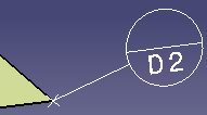 |
| Curve or wireframe plane | Open arrow |
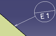 |
| All other cases | Filled circle |
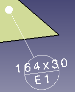 |
|
|
|
Datum Target Indicator for Datums
|
For datums established using datum targets, an indicating label appears to
the right side of the datum. The label: |
|