-
Click Extended Cylinder Construction Geometry and select a cylindrical pin or a cylindrical hole.
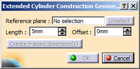
The Extended Cylinder Construction Geometry dialog box appears.
-
Define the length in the Length box.
-
Define the offset in the Offset box.
-
Define a suitable plane in the Reference plane box.
The selected plane must be perpendicular to the selected cylindrical pin or hole.
The Create framed dimension(s) and OK buttons are now available for selection.
You cannot create framed dimensions while working with ASME 14.5:2009 standard. -
Click Create framed dimension(s).
- The basic dimension feature is created, if it does not already exist. If
you are working with ISO 5450:2011 standard, a
 symbol appears next to
the basic dimension. If you are working with ASME 14.5:2009 standard,
the symbol does not appear.
symbol appears next to
the basic dimension. If you are working with ASME 14.5:2009 standard,
the symbol does not appear. - If the offset value is not zero, a minimum distance is present between the extended cylinder and the reference plane.
- The basic dimension feature is created, if it does not already exist. If
you are working with ISO 5450:2011 standard, a
-
Click OK.
The extended cylinder is created. An Extended Cylinder.x node is created under Constructed geometries in the specification tree.
Note: The representation of the created extended cylinder is dependant on the standards:- With ISO standards, a cylindrical representation is created.
- With ASME standards, a line representation is created at the axis of the cylinder.
The extended cylinder construction geometry is retained when the standard of a feature is changed from ISO to ASME using the feature properties.