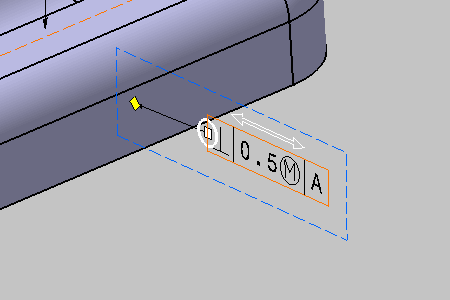
Geometrical tolerances are specifications included in a tolerance frame.
-
Click Geometrical Tolerance
 in the
Annotations toolbar.
The Geometrical Tolerance dialog box is displayed.

The Tools Palette is displayed according to the type of face selected depending on the canonicity. In this scenario the Tools Palette is not used. For more information, refer to Propagating Geometry Selection for Feature Creation.
-
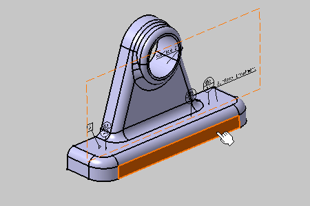
Select the front planar surface as shown:

-
In the Geometrical Tolearance dialog box, you can perform the following operations:
- In the Add Tolerance section, click the required
tolerance indicator to add it to the current feature.
You can add as many tolerances as required.
The tolerance indicator is added below the previous one in a separate line. Each line is represented by tabs in the Edit Tolerance section. - In the Edit Tolerance section, you can replace
the selected tolerance indicator with another one from the list.
In the list, you can also select Remove Line to remove the selected line. This option is unavailable if the selected tolerance line is the only one in the list. - In the Edit Tolerance box, add the tolerance
value.
In the Edit Tolerance section, you can also select engineering symbols. - In the Reference boxes, add references.
You can add the first reference, by default. To add the second and the third reference, the previous reference must be added. You can also select engineering symbols. The references can be cleared.
In the Datum systems and datums box and the Datum features box, select the existing datum systems and the datum features.
- In the Auxiliary Feature Indicators list, select
a local indicator.
The engineering symbols list and datum feature identifier box are available for modification. - In the Auxiliary Feature Text Indicator box, add
an indication text.
You can also select engineering symbols. - In the Global Text Indicators boxes, add an upper
and a lower text.
You can also select engineering symbols.
-
The symbols selected in in the Geometrical Tolerance dialog box are saved as a user preference for each field.
-
You can add maximum three non-identical local identifiers for a single tolerance.
-
- In the Add Tolerance section, click the required
tolerance indicator to add it to the current feature.
-
Click OK.
The geometrical tolerancing annotation is attached to the 3D part.
The geometrical tolerance entity is added to the specification tree.
