- Creating an automatic constructed geometry allows you to create associative wireframe geometry according to the context or represented geometry.
- The lifecycle of an automatic constructed geometry is managed by the application.
- To customize the constructed geometry options, see Constructed Geometry.
- The constructed geometries are grouped under the Construction geometries section in the Annotation Set section.
- Querying an annotation created on a constructed geometry (created automatically or managed manually) highlights automatically the constructed geometry itself and its related geometry.
- Point from:
- Sphere: the sphere center
- Cone: the cone vertex
- Torus: the torus center
- Circle: the circle center
- Intersection of a plane and a line: the intersection must exist.
- Axis from:
- Cylinder: the cylinder axis
- Cone, a torus or a revolution surface: the revolution axis
- Intersection of two planes: the intersection must exist.
- Curve from:
- Electrical feature.
- Plane from:
- Cone: from the cone vertex to the infinite
- Torus: the plane normal to its axis passing through its center
- Angular plane from:
- One plane and one line: plane and line must be parallel.
-
Two user surfaces or geometrical elements:
-
One cylindrical and one planar
-
One revolute and one planar
-
Two non-parallel cylindrical user surfaces or geometrical elements
-
Two non-parallel revolute user surfaces or geometrical elements
-
- Median plane from:
- Two planes: planes must be parallel.
- Passing plane from:
- Two planes: planes must be coplanar
- One plane and one line: line must be on the plane
- One plane and one point: point must be on the plane
- Two lines: lines must be parallel or intersecting
- One line and one point: point must not be on the line
- Three points.
- Thread from:
- Part feature.
- Circle from:
- Cone: from the cone vertex to the infinite, except the cone vertex.
- Intersection of one cone and one plane: the plane must be perpendicular to the cone axis, the intersection must exist.
- Intersection of one cone and one cylinder: cone and circle axes must be coaxial, the intersection must exist.
- Intersection of two cones: cone axes must be coaxial, the intersection must exist.
- Circling cylinder from:
- Three lines (or axes) at least and passing through these ones: lines (or axes) must be parallel and a solution must exist.
- Reference cylinder from:
- A line (or an axis) to define its reference cylinder axis, and passing through one or more lines (or axes) to define its radius: selected lines (or axes) must be parallel and a solution must exist.
- Improve the highlight of the related geometry, see Highlighting of the Related Geometry for 3D Annotation.
-
Select the surface as shown.
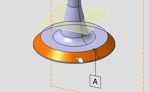
The Constructed Geometry Creation dialog box appears. 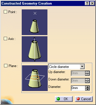

The Tools Palette is displayed according to the type of face selected depending on the canonicity. In this scenario the Tools Palette is not used. For more information, refer to Propagating Geometry Selection for Feature Creation.
-
Check Axis and Plane as geometries to be generated and click OK in the dialog box.
The axis and the plane are created in the geometry. See also Constructed Geometry options for graphic properties and limits. 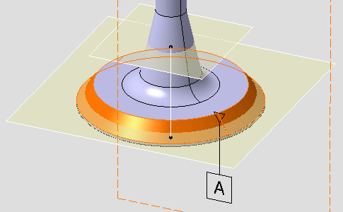
In the specification tree, Cone Axis.1 and Gage Plane.2 representing the created axis and plane geometries are added to the Construction geometries section. 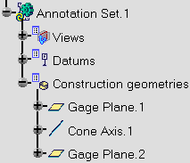
-
Click OK.
-
Click the Constructed Geometry Management icon:

-
Select the surface as shown.
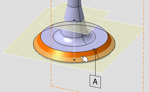
The Constructed Geometry Management dialog box appears and displays the two created geometries and their creation mode, where User Surface.8 and User Surface.9 are representing geometry elements of the axis and the plane respectively. 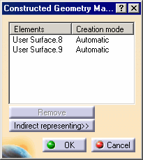
-
Click OK.