This task explains how to define flattening parameters.
This should be done before using any other function of the Electrical
Harness Flattening workbench.
Open the 3D-Install Harness document.
-
Open a new product document using the File > New... command.
Choose the Product type. -
Click Harness Flattening Parameters
 .
.The Harness Flattening Parameters dialog box opens on the General tab:
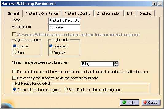
Keep the default values: - xy plane as the Active plane
-
3D
Harness Flattening without mechanical constraint between
electrical component
selected or
cleared depending on the setting in the Tools >
Options
> Electrical Harness Flattening
> General
tab
For more information refer to Electrical Harness Flattening. - Coarse as the Algorithm mode and Standard as the Angle mode
- 5 degrees as the Minimum angle between two branches.
-
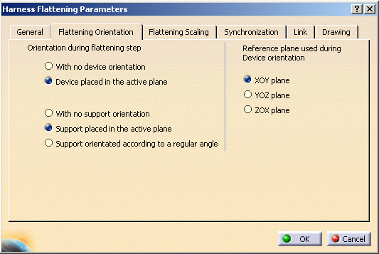
Select the Flattening Orientation tab.

- If you want to keep the tangency of the connector with the bundle segment, the With no device orientation option (under Flattening Orientation tab) should be cleared and the Keep existing tangent between bundle segment and connector during the flattening step option (under General tab) should be selected.
- If you want to keep the device orientation, the With no device orientation option (under Flattening Orientation tab) should be selected and the Keep existing tangent between bundle segment and connector during the flattening step option (under General tab) should be cleared.
- It is not possible to respect both the options. The device
tangency may go out of the flattening plane if the device is
aligned with the flattening plane normal. This will lead to
bundle segment curve update failure.
Hence, in case both the options are selected, the Keep existing tangent between bundle segment and connector during the flattening step option (under General tab) is given priority, and the tangency is maintained, however device orientation is lost.
-
Specify the orientation of the device during the flattening step:
Select Device placed in the active plane.
The local Z axis of the device is positioned perpendicular to the active plane specified in the General tab of this dialog box. -
Specify the support orientation:
Select Support orientated according to a regular angle.
The orientation by default of the supports keeps the real position (angle between 0° and 360°). Supports will be placed according to the closest regular angle they have in 3D. They are four regular angles (0°, 90°, 180° and 270°). It enables you to prevent bundle segments from twisting. -
Specify the reference plane to be used for the device orientation.
The XOY plane is selected by default.
XOY plane used to define devices
YOZ plane used to define devices
ZOX plane used to define devices
-
Click OK to validate.
The parameters you have entered will be automatically
applied to the other functions available in this workbench. You will be
able to modify them at any time during your session by double-clicking the
Flattening Parameters icon in the specification tree.
To know more about the different Harness Flattening Parameters, click
here.