Edit a Single Producibility
-
Click Edit Producibility Table
 in
the Flattening toolbar.
in
the Flattening toolbar.
-
Check the deformation value of the material applied to a ply.
- Select the line of the ply in the table.
- Check the status in the Max. Shear and
Max. Dev columns.
No circle indicates the deformation is below the warning limit.
A yellow circle indicates the deformation is between the warning and the limit values.
A red circle indicates the deformation is above the limit value. - Check the warning and limit values of the material
applied to the considered ply under Material Properties.
These values are part of the Materials properties in Composites Parameters.
-
Select one row and click Create.
A new producibility parameters set is created at the end of any existing sets for the selected ply. Select one row and click Edit.
- Edit the current producibility in the dialog box that opens.
- Click Preview.
The results for the simulation are added.
-
Select one or several rows and click Delete.
The selection is deleted. -
Select one row and click Copy, Cut or Paste to perform the corresponding actions.
-
Select one or several rows and click Run.
- Select the Show results check box to display the simulation results in the graphic area. You have to select the plies one by one to see them.
- Select the Show multiple results check box to display the computed fiber propagation of several selected producibilities in one shot.
The corresponding simulation is run and the result status is displayed.
In a few cases, the position of seed points may lead to an invalid rosette transfer and incorrect fiber directions. A warning is displayed when this problem is detected.
-
Click OK to validate and exit the dialog box.

Edit a Multi-Selection of Producibilities
-
Start Edit Producibility Table
as explained above. -
- Select stacking entities as explained in Using the Stacking Management.
- Alternatively, select stacking entities in the graphic area.
- Click OK in the multi-selection box to revert to the Edit Producibility Table.
Plies and/or cut-pieces are put in the selection stack.
Related producibilities are selected and highlighted in the Edit Producibility Table.
If several producibilities are found under a given ply or cut-piece, only the current producibility is selected.
Edit becomes available.
Note that the selected elements must have a producibility with the same manufacturing propagation type. -
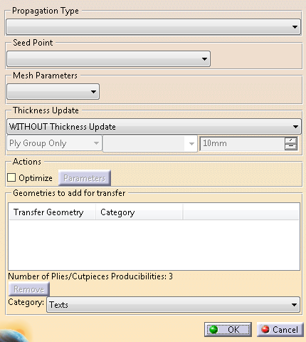
The list of editable parameters depends on the manufacturing propagation type:- For braiding:
- Propagation type
- Parameters related to the thickness update.
- For Hand-Layup:
- Propagation type
- Seed point selection (selection/indication/geometrical center)
- Mesh parameters (scaled or explicit)
- Parameters related to the thickness update.
- For Fiber Placement:
- Propagation type
- Seed point selection (selection/indication/geometrical center)
- Fiber initialization curve
- Warp/weft parameters
- Mesh parameters (scaled or explicit)
- Parameters related to the thickness update.
Regarding lists, if the selected elements share the same value for a given parameter,
this value is displayed in the list. Otherwise, the list is left blank.- Either leave the list blank.
Each selected elements keeps its original value. - Or select a value from the list.
This value is applied to all selected elements.
- For braiding:
For producibilities by hand layup, you can activate the optimization and set its parameters.
Proceed as explained in Creating a Producibility for Hand Layup.-
Click OK to validate.
Transfer 3D Geometry to 2D
-
Start the Edit Producibility Table as explained above.
Select several producibilities and click Edit.
-
Select geometries to transfer (curves or points).
- Available if the plies and associated producibilities share the same reference surface.
- Curves must lie on the reference surface of the ply, and at least partially on the ply shell. A message is displayed if this is not the case.
- Undo/redo is not supported.
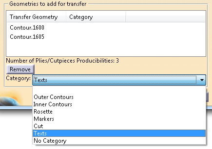
The number of Plies/Cutpieces producibilities is displayed.
Selected curves or points are added to the Geometries to add for transfer list and added to all possible plies or cut-pieces.
-
Select geometries to transfer, sharing the same category or not.
-
Select a new category from the list.
The new category is applied to all selected geometry to transfer.
If you add geometries to transfer with no defined category, the last category you have selected is proposed by default. You can edit it. -
If necessary, select Remove to remove geometries from the list.
To globally remove existing transfers from existing producibilities. - Identify the transfers to remove from producibilities.
- Multi-select these producibilities, and start the Edit Multiple Producibilities dialog box.
- Select the geometries to remove in the
graphic area.
They are added to the list and highlighted. - Click Remove.
-
Validate.
At flattening, the transferred geometries are created as Geometry Transfer.
![]()