The typical process is:
- Split the work on a large surface into several parts and create grid elements on the different parts.
- Import the created grid elements into an empty part, using Grid Definition Merge.
- Create the plies group from the virtual stackings in the resulting merged part.
- If need be, edit the design in the original parts and synchronize them with the merged part.
- Once the design is defined, and the stackings are generated, assemble the plies groups in the resulting merged part.
This task shows you how to merge the
grid definitions from these parts into a single one.
Be aware that only
Master Stacking Sequence mode is supported.
As this is a collaborative work, launch Prepare for Synchronization on each part to merge, before selecting them. This adds collaborative information for further synchronizations.
In short
- Create the surface and the Composites parameters.
- Launch the Prepare for Synchronization.
- Split the work on the surface into several parts.
- On each part, only create the corresponding design (grid panel, grid and grid virtual stacking).
- Merge the designs into an empty part.
- You can now create Plies groups on the merged part.
- Use Assemble Plies Groups to generate one merged plies group.
This is an iterative process, where you can select several parts to merge. However, make sure that
- All parts to merge are specified using a Master Stacking Sequence,
and that the Master Stacking Sequence is exactly the same for all parts.
Grid Definition Merge can be started from an empty open part with no Master Stacking Sequence. However the above restriction applies to all selected parts to merge. - The support surfaces of each grid panel are geometrically
identical.
Grid features can overlap each other, but overlapping cells cannot have the same layers according to the Master Stacking Sequence (Each layer must be different).
-
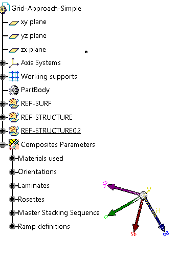
Open an empty part, or one containing Composites Parameters and a Grid definition
(GridSolidGA02-GridAndPliesMergeStarter.CATPart)
-
Click Grid Definition Merge
 in the Grid Design
toolbar.
in the Grid Design
toolbar.
-
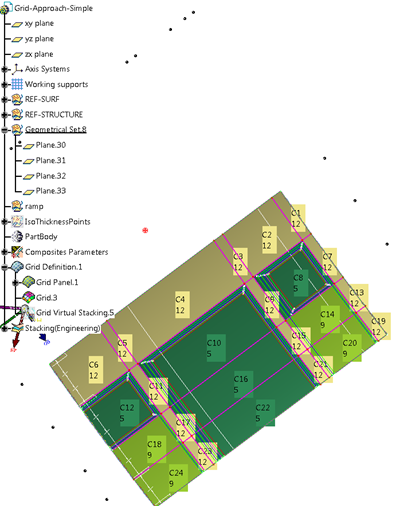
Click ... and select the parts to merge
(GridSolidGA02-GridAndPliesMerge01.CATPart
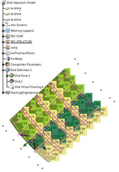
and GridSolidGA02-GridAndPliesMerge02.CATPart)
They must be different from the original part. -
Prepare for Synchronization sets collaborative information on each feature.
This helps for further synchronization process with a merged part.
However, some parts already have collaborative information (using the engineering and manufacturing collaborative commands) and it may lead to invalid behavior.
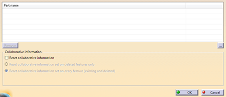
Select the Reset Collaborative Information checkbox to avoid these issues. -
Click OK.
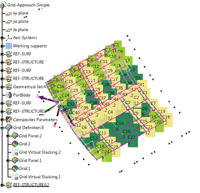
Grid entities from the open and selected parts are merged.- The grid panels, grids and virtual stacking from the open part and the selected parts are merged and gathered under Grid Definition.
- Composites parameters from the selected parts are merged with those of the open part. If they already exist in the open part, they are not duplicated.
- Only one copy of materials, orientations, laminates, rosettes is kept.
- Material comparison is done from the MaterialID.
- Orientation comparison is done from the orientation name and orientation value.
- Laminate comparison is done from its type (Thickness law, stacking sequence or Master Stacking Sequence) and from its specifications in the given type.
- Rosette comparison is done from the coordinates and vectors.
- If they do not exist in the open part, they are created (Composites Parameters node, Master Stacking Sequence, Grid Definition node).
- Ramp definitions are always imported and duplicated, even if they already exist.
![]()