Basically, you import a file that contains information to create elements such as plies groups, sequences, grid reference elements, ramp supports, plies, contours. The elements are created or updated in the graphic area. Likewise, you can export the data of a design to a spreadsheet and modify the data in the spreadsheet. When you re-import that spreadsheet, the design is updated accordingly. Diagnoses help you correct possible errors.
Import the Model Design
-
From the flyout in the Grid Design toolbar, click Import Design
 .
.
-
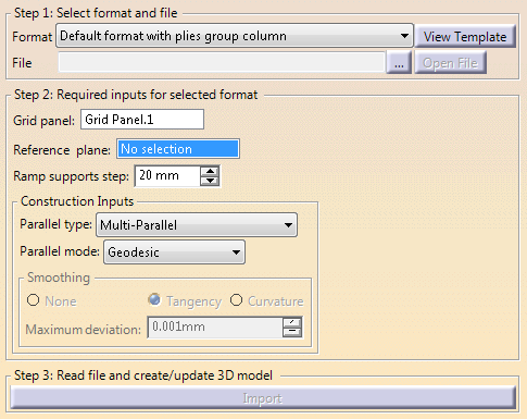
Select the format of the file to import from the list.
Optional: Click View Template to visualize the format.
Default templates are proposed and stored under ./startup/composites/TemplateReadWriterDefault.xls and ./startup/composites/TemplateReadWriterDefault2.xls.
The proposed formats are:- Default
format with plies group column with the
following template:
Plies Group Sequence Ply Material Orientation Starting Plane End Plane LEFT LIMIT Offset RIGHT LIMIT Offset 2 - Default
format without plies group column with the
following template:
Sequence Ply Material Orientation Starting Plane End Plane LEFT LIMIT Offset RIGHT LIMIT Offset 2 - Long skinny part
format (4 limits & 4 offsets) with the following
template
Plies Group Sequence Ply Material Orientation Limit 1 Offset 1 Limit 2 Offset 2 Limit 3 Offset 3 Limit 4 Offset 4
- Default
format with plies group column with the
following template:
-
Click ... and select the file to import.
Optional: Click Open File to open the file.
The spreadsheet contains the names of the sequences, plies, ply groups, materials, orientations, starting and end plane, left and right limit (with possible offset). -
For Default format with plies group column and Default format without plies group column. - The Grid Panel
-
The Reference plane:
The data found in the spreadsheet are as follows:

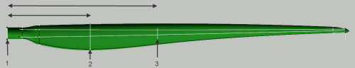
They are used to create the grid reference elements, taking the reference plane into account. In the images below:- 1 is the reference plane
- 2 îs the starting plane. 2000 is its distance to the reference plane (smaller double-headed arrow).
- 3 is the end plane. 4000 is the distance to the reference plane (longer double-headed arrow).
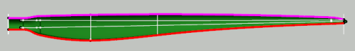
- The left limit is shown in pink.
- The right limit is shown in red.
- The Ramp support step.
- The Ramp Support Fallback Strategy via More. See Generating the Plies from the Virtual Stacking for more information.
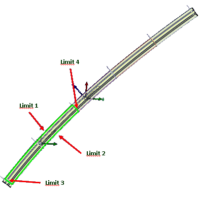
For Long skinny part format (4 limits & 4 offsets)
- The Grid panel that contains the Reference Elements (S.1...S.6, F.1...F.6) to create the grid reference elements.
- The Ramp supports step.
- The Construction Inputs such as the Parallel type and Parallel mode
-
Note: The Ramp supports step is the default step used to create all the automatic ramp supports. If the offset values are not a multiple of this step, the import stops.
- Either edit the offset values that are not a multiple in the spreadsheet and restart import.
- Or continue and switch all the ramp
supports with a value that is not a multiple of the
step from automatic to custom.
- The parallels are created in a new geometrical set.
- The custom ramp supports are created using the parallels.
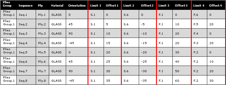
For example, let's consider the creation of Ply.4 with an initial Ramp supports step of 10.
- Create Limit 1: S.1 with Offset=15
- 15 is not a multiple of 10.
- A Custom Curve is created and aggregated to the Grid Ramp Support associated to S.1
- Create Limit 2: S.6 with Offset=-15
- 15 is not a multiple of 10.
- A Custom Curve is created and aggregated to the Grid Ramp Support associated to S.6
- Create Limit 3: F.1 with Offset=-20
- 20 is a multiple of 10.
- A Parallel is created and aggregated to the Parallel/Parallel Grid Ramp Support associated to F.1
- Create Limit 4: F.3 with Offset=-20
- 20 is a multiple of 10.
- A Parallel is created and aggregated to the Parallel/Parallel Grid Ramp Support associated to F.3
- Create the contour of the ply from the 4 curves.
- Create the sequence and the ply with GLASS as material, -45 as orientation and the above contour.
When you click OK, this information is stored and will be proposed the next time you enter the command.
Click Import.
Import Composites Design reads the file and creates or updates the design from the data it contains.- The 3D viewer is updated accordingly.
- The number of plies created, updated or with errors is given.
- The resulting plies are listed in the dialog box, with their status.
Select one line in the dialog box.
- A reframe is done in the 3D viewer.
- Information and error flags, if any, give the distance to the reference plane or the name of the element and more details when you place the cursor on them.
- When relevant, causes of error such as missing material, orientation, update errors, ... are listed in the dialog box.
-
Click OK to validate and exit the dialog box.
Export the Composites Design
-
From the flyout in the Grid Design toolbar, click Export Design
 .
. -
Select the format of the file to export from the list.
Optional: Click View Template to visualize the format.
Default templates are proposed and stored under ./startup/composites/TemplateReadWriterDefault.xls and ./startup/composites/TemplateReadWriterDefault2.xls. -
Click ... and enter the storage location of the file to export.
Optional: Click Open File to open the file. -
Select the type of elements to export: The Complete Stacking or a Selection of Groups.
In this case, select the groups to export in the list below. -
Click Export.
- The export file is created, with the same information as described for import.
- When relevant, diagnoses are displayed as described above for the import.
- Once you have modified the values in the spreadsheet, you can re-import it to update the design.
![]()