This task shows you how to generate a top surface from virtual stackings in one shot: From the virtual grid design, Top Surface from Virtual Stacking analyzes the plies to generate, identifies iso-thickness areas, automatically creates junction lines and provides a top surface.
You must have created virtual stackings.
-
Click Top Surface from Virtual Stacking
 in the Top Surface & Solid toolbar.
-
Select one or several virtual stackings lying on the same surface.
-
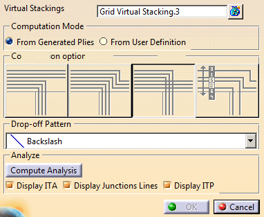
If plies have already been generated from the virtual stackings, select From Generated Plies.
The top surface matches the plies. -
Otherwise, select From User Definition and select an algorithm.
-
 Weight saving
manages the drop-off pattern locally:
Weight saving
manages the drop-off pattern locally:

The closest ramp support curves are used for the plies corresponding to the longest ramp entity.
The drop-off pattern is managed ramp entity by ramp entity.
-
 Minimum Crossing
manages the drop-off pattern globally:
Minimum Crossing
manages the drop-off pattern globally:

-
 Minimum crossing & Weight Saving
manages the drop-off pattern from three criteria,
Minimum crossing & Weight Saving
manages the drop-off pattern from three criteria,
respectively length, height and surface (L*H).
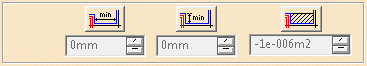
Click the corresponding icon to activate the criterion and enter the required value.
If one measure is below the criterion, the staggering is not created. -
 Drop-off order based on layer level
uses the layer level of each virtual sequence as a drop-off
order value to stagger plies.
Drop-off order based on layer level
uses the layer level of each virtual sequence as a drop-off
order value to stagger plies.
Make sure the layer levels are unique.
Available when layer levels are defined on each virtual sequence.
See About Master Stacking Sequence for more information.
Drop-off pattern is not available with this option.
-
-
Optional: Select a drop-off pattern.
The drop-off pattern takes the orientation of plies into account.
When working in Master Stacking Sequence mode, the layer key of each virtual sequence is used as drop-off order value. The drop-off pattern choice is disabled. -
Click Compute Analysis and select the required options.
A view of Iso-Thickness Areas (in green, with height), junction lines (in white) and ITPs if any (in yellow) is displayed according to the selected options.
A top surface is generated. It is editable for update.
![]()