This task shows you how to use the junction lines wizard to create,
check, validate junction lines,
and find locations where they are
missing or incorrect.
You must have created a Grid.
The junction lines created are associated to the ramp supports.
This
means that modifications that impact them will be properly propagated
and handled
but for instance, adding a ply will not modify the line
created.
or open the GridJunctionLines01.CATPart document.
-
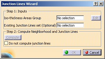
Click Iso-Thickness Junction Wizard
 in the Top Surface & Solid toolbar.
 -
Choose to compute or not junction lines.
By default, the check box Do not compute junction lines is not selected. -
Select the 3D display options you need
- Reframe on selected group,
- Reframe on next group that is not checked,
- Directly or Animated (defining how the reframes are done),
- Hide/Show Stacking.
-
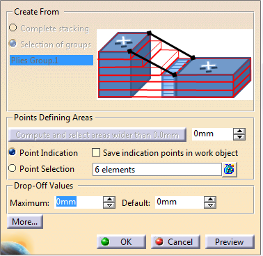
In the dialog box, select one or several lines
and click Validate to validate the corresponding junction lines.
As you select a line in the dialog box, a reframe is done in the authoring window
according to the options you have selected in the previous step -
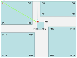
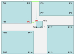
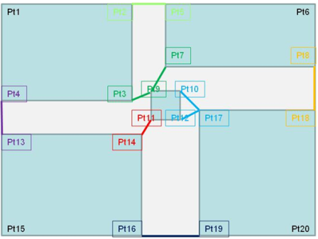
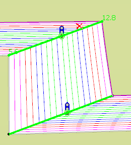
Drag the cursor over a vertex.
The two ramp supports that intersect at this vertex are displayed. -
Click a point and drag the cursor.
A dotted lined is displayed as you drag the cursor. - It is red, until you pass the cursor over another point.
- If that point belongs to another iso-thickness area, or
is a GSD point ,
the dotted line turns green, meaning a junction line will be created between those two points. - If that point belongs to the same iso-thickness area,
this iso-thickness area will be relimited by the dotted line.

The iso-thickness area can be relimited or trimmed. -
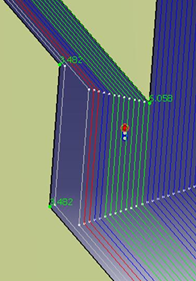
To remove any potential or validated junction line, drag the cursor over the line until a red cross appears.
Click that red cross. The junction line is removed from the preview and will not be created. -
Click a traffic light.
Its junction lines are validated, and you go to the next group of points to validate. -
When you have checked and validated all the groups, click OK to validate exit the dialog box.
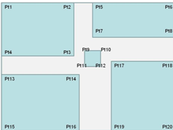
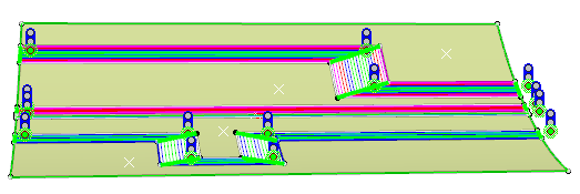
Junctions lines are created either in the geometrical set containing existing junction lines you have selected,
or in a new geometrical set named Junction lines (Generated by wizard):- Junction lines previewed as solid green lines, i.e. validated by you, are created.
- Junction lines previewed as dotted green lines, i.e. not
validated by you, are not created.
A message is displayed. - Junction lines previewed as blue lines, i.e. existing and not modified , remain unchanged.
- Junction lines that you have removed from the preview are removed.
Iso-thickness areas are relimited, if need be.
The geometry required to perform this relimitation is added under the iso-thickness area.


![]()