Read About Iso-Thickness Areas for more information, in particular about limits and possible problems.
-
Click Iso-Thickness Areas
 in the Top Surface & Solid toolbar.
The Iso-thickness Areas dialog box is displayed:
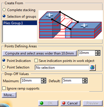
The plies groups found in the model are displayed in the dialog box. -
Select core sampling points to define the iso-thickness areas manually:
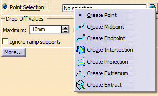
- Either select the Point Selection option, and select exisiting points in the 3D viewer.
- Or select the Point Indication option and pick locations in the 3D viewer.
- Then decide if you want to save those indication points in the in work object or not.
- If required, create
additional points using
the contextual menu.
- You can mix both options, e.g. select existing points, then indicate points to complete the selection.
- Multi-selection is
available through
 and the dialog box
below:
and the dialog box
below:
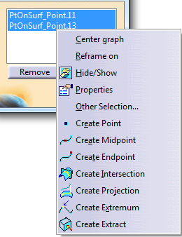
- The number of points selected or indicated is displayed in the dialog box.
-
To define the iso-thickness areas automatically:
- Enter a value in the
spinner under Points
Defining Areas.
This value represents the minimum width that makes an iso-thickness area selectable.
By default, this value is set to the maximum drop-off value.
It varies with the maximum drop-off value.
You can also edit it manually. - Click Compute and
select areas wider than
...
- This button is available only once in creation mode.
- This button is not available in edition mode.
We recommend that you consider this automatic mode as an initialization step,
to be completed manually.- Potential iso-thickness areas are computed.
- Those wider than the value entered are automatically selected.
- A progress bar is displayed.
- Indication points are created and selected as you would have done manually.
- Enter a value in the
spinner under Points
Defining Areas.
-
For models not designed with a grid approach,
define the Drop-Off Values used to compute the bottom of slope.By default:
- Maximum is set to 0
if no ramp support has
been defined,
or to the maximum step of slope found in all ramp supports of the model otherwise. - Default is set to 0
if no ramp support has
been defined,
or to the minimum step of slope found in all ramp supports of the model otherwise.
- Maximum is set to 0
if no ramp support has
been defined,
Optional: Select the Ignore ramp supports check box.
This is useful when ramp supports do not fully fit your requirements.
(The first curve in the ramp support is not the top one, or you need to extend plies by a symmetry).
This options applies to the iso-thickness areas group, not to individual iso-thickness areas.
When this check box is selected, the shells are relimited by the bottom slope,
computed with the distance to neighboring ply contours, with a geometrical approach.
If this automatic computation fails, you can relimit specific shells using standard relimitation commands.
-
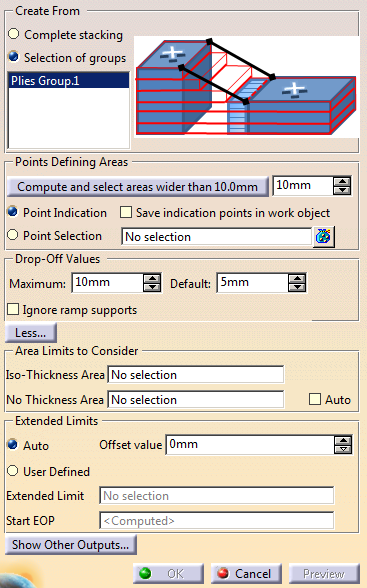
Click More...
-
Select a contour or Composites geometry and the required method to create limits.
-
Iso-Thickness Area: Creates the ITA group only inside the
selected area (one selection permitted).
The top surface generated from this ITA group is limited by the contour or geometry. - No Thickness Area: Creates the ITA group with
all the areas found inside the selected contour or geometry,
even it the areas have no plies, thus no thickness with
respect to the support surface.
The top surface generated from this ITA group contains these areas with no thickness. - Make sure the Not Thickness Area does not intersect a ply contour.
-
Iso-Thickness Area: Creates the ITA group only inside the
selected area (one selection permitted).
-
Extend the limits of the ITA Area:
-
User Define: Select an
Extended limit (Contour or Composites geometry), and an optional
Start EOP (Contour or Composites geometry) to specify the side of the ITA to extend.
- If you do not select a Start EOP, it is computed as the full ply boundary of all selected plies groups.
- Start EOP and Extended limit must be larger than all selected plies.
- Auto: Enter an offset value (Extended limit and
Start EOP are automatically computed).
- The offset value cannot result in a top surface larger than the support surface.
- Auto does not support multi-domains EOP.
-
User Define: Select an
Extended limit (Contour or Composites geometry), and an optional
Start EOP (Contour or Composites geometry) to specify the side of the ITA to extend.
-
Click Show Other Outputs:
Under Modifiers, define an additional thickness.
- It is entered as a ratio of the current thickness, e.g. 0.1 means 10% of the current thickness.
- In creation mode, it defines the additional thickness of all the iso-thickness areas of the group.
- In edition mode:
- If
an
additional
thickness
previously
applied
to all
the iso-thickness
areas of
the
group,
the modified additional thickness applies to all the iso-thickness areas of the group. - If
an
additional
thickness
applied
only to
some iso-thickness
areas of
the
group,
you can choose to apply the modification only to those iso-thickness areas or
to all iso-thickness areas of the group.
- If
an
additional
thickness
previously
applied
to all
the iso-thickness
areas of
the
group,
- By default, Additional thickness ratio is set to 0.
-
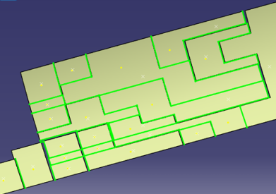
Click Preview to check any changes.
The edges of the iso-thickness areas that correspond to the bottom slopes are highlighted in green.
-
Click OK to validate and exit the dialog box.
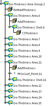
The iso-thickness areas group and the iso-thickness areas are created.
The contour of the iso-thickness area is relimited by the bottom of the ramp
(i.e. last ply+1 on ramp support) if the plies are created with the grid approach
(i.e. if they are based on ramp support).
In that case, the iso-thickness area turns yellow.
If the iso-thickness area cannot be relimited by the bottom of the ramp, it turns pink (unless you chose to ignore the ramp supports).
A warning is issued if an iso-thickness area needs to be reworked.You can modify the shape of an iso-thickness area before creating the solid.
When the core sample point of an iso-thickness area may have become invalid,
a mask at the iso-thickness area node indicates that the feature needs to be updated.If you modify an iso-thickness area, and add or modify core sample points,
iso-thickness areas that have not been impacted do not need to be recomputed. -
Double-click an iso-thickness area to edit it.
Right-click an Iso-Thickness Shell to access its contextual menu
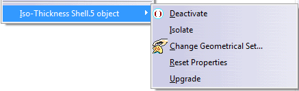
![]()