 |
-
Do one of the following:
- Right-click a ramp support in the specification tree and
select Definition in the contextual menu.
- Double-click a Grid Ramp Support
node.
- Select a reference
element and click Ramp Support
 in the Grid Design toolbar.
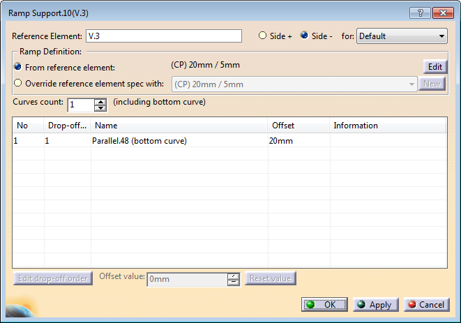
The Reference Element name is given for
information. It is not editable.
|
-
Select Side + or Side -, and a ramp
definition from the list. -
Select From reference element to work
with the ramp definition specified on that element.
The ramp
support is linked to the default ramp definition, or to the ramp
definition specified for a sub-staggering sector.
-
If required, click Edit to modify this
ramp definition and edit the reference element.
For more
information, see Specifying a Ramp
Definition.
Note: Some restrictions may apply when modifying
the reference element from the ramp support.
If the ramp
definition is modified or replaced by another one at the reference
element level, that ramp support is updated. -
Alternatively, select Override reference element spec with,
for example to manage multi-slope drops. The ramp definition currently applied
to the reference element is proposed in the list.
- Select another ramp definition from the list.
- Or click New to specify a new ramp definition.
For more information, see Specifying a Ramp
Definition.
- Optional: Change the Offset value.
The ramp support is used to generate plies for the selected default ramp definition or sub-staggering, but if the ramp definition is modified on the reference element, the ramp support is not up-dated. |
-
Specify the number of curves to create
(You can
add or remove curves, except for Custom ramp definition type).
If relevant, the last curve is marked as (bottom curve). -
If required, edit the drop-off order of the curves for plies
generation.
Do so:
- To invert the order of all curves.
- When plies need to be dropped two by two. For example, to reduce
the number of generated curves, indicate that the first curve is
used to drop the first and second plies, the second curve to drop
the third and fourth plies, and so on.
|
A Ramp Support node is created under the Reference
Element.
It contains the ramp support curves. They can be
- Multi-Parallel Curves
- Parallel/Parallel Chained curves
- Offset/Offset curves
- Offset/Parallel curves
- Angle to Curve curves.
- Between Two Curves curves.
- Custom curves.
|