After this analysis is performed, you are rerouted to the standard Angle Cut command.
-
Click Grid Angle Cut Wizard
 in the Grid Design toolbar.
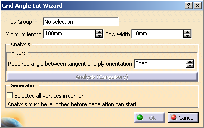
The Grid Angle Cut Wizard dialog box is displayed.
-
Define the analysis criteria:
-
The wizard:
- Finds all the ply contour vertices with discontinuities in tangency,
- Ignores those where the discontinuity is already the result of an angle cut,
- Checks the angle between the tangents at the vertices
and ignores the vertices
where this angle is too large, e.g.- This angle is valid:
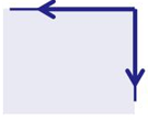
- This angle is invalid:
- This angle is valid:
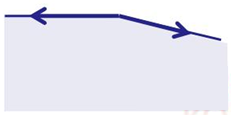
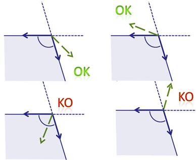
- Checks the angle between each tangent and the ply
orientation (displayed in dash green below)
and ignores the vertices where this angle is lower than Minimum angle ply orientation vs tangent, e.g.- This angle is valid:
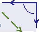
- This angle is invalid:
- This angle is valid:
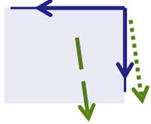
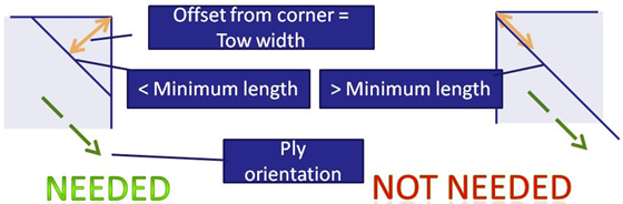
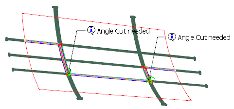
- Finds out whether an angle cut is needed or not: it
computes an offset from the vertex,
equal to the Tow width, parallel to the direction of the ply orientation.
An angle cut is required if the length of this curve is smaller than the Minimum length.
- Ignores vertices where the ply orientation is not
consistent with the tangents.
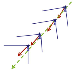
Then, the wizard groups the vertices coming from the same ramp support,
according to orientation and tangency criteria, e.g. below the yellow star stands for vertices
with the same orientation, the blue star for vertices where the orientation differs,
and the green star for vertices where the tangents differ.
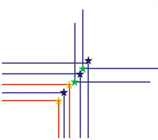
Within a given group, the vertices are ordered according to their abscissa along an average bisector.
Those groups are displayed in the 3D viewer.
-
Click one label.
Optional: Check Selected all vertices in corner to select all the vertices, whatever their orientation is.
The Angle Cut Definition dialog box is displayed. -
Proceed as explained in Creating Angle Cuts Manually and click OK in the Angle Cut Definition dialog box.
When the angle cuts are created for a group, its labels disappears, and you can proceed with the next group. -
Once you are done with all the groups, click OK in the Grid angle cut wizard dialog box to validate and exit.
Corresponding Ramp Definitions are created in a dedicated node, under the Ramp Definitions in Composites Parameters.
It is displayed according to option set in Tools > Options
![]()