Click Grid Angle Cut
 in the Grid Design toolbar.
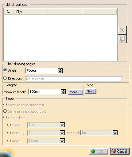
The Angle Cut Definition dialog box is displayed:
-
Pick the vertices to process.
- Click
 to remove the selected vertex from the selection.
 - Click
 to propagate your selection to the next vertices downwards.
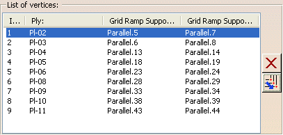
 - For each selected vertex, the dialog
box is updated with its index,
the name of the ply it belongs to, and the name of its two ramp supports.
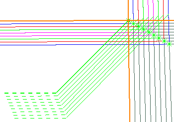
- The vertices are highlighted in the 3D window.
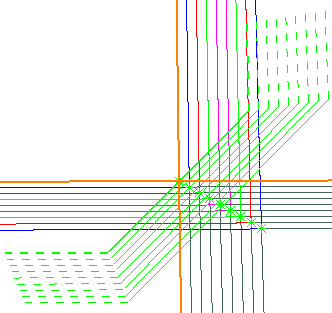
- A preview of the result is displayed.
- A red display indicates the result is not valid.
- Click
-
Click Next under Side to switch to the next possible result:
or
Define the Fiber draping angle:
- Select Angle and enter an angle value.
- Or select Direction and
select an existing element
or create one with the contextual menu of Direction.
-
Define the Length:
- Define the Minimum length, i.e. the
minimum tape length.
- Click More to define
extrapolation lengths.
Make sure the extrapolation distances are sufficient to cross all the plies that will have an angle cut,
and that you have picked the vertices in proper order.
Otherwise, a message warns you that the minimum length could not be respected for some plies.
- Define the Minimum length, i.e. the
minimum tape length.
-
Under Slope, define the staggering.
Once vertices are selected, Same as ramp support is replaced by the actual values, e.g.
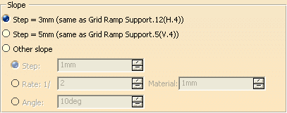
- either as Same as ramp support #1 (as found in first column Grid Ramp Support),
- or as Same as ramp support #2 (as found in second column Grid Ramp Support),
- or as an Other slope.
When this option is selected, the Slope value parameters become available.- Step is the length between the angle cut edges,
- Rate is the ratio that defines the slope,
- Angle is the angle of the drop-off,
- Material is the expected material thickness.
See Editing Ramp Supports for more information.
-
Click OK to validate and exit the Angle Cut Definition dialog box.
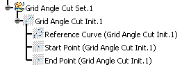
A Grid Angle Cut Set is created:
Corresponding Ramp Definitions are created in a dedicated node, under the Ramp Definitions in Composites Parameters.
It is displayed according to option set in Tools > Options.
About the Angle Cut init Definition Dialog Box
In the Grid Angle Cut command, this dialog
box is initialized by the selections you have made.
You can also access the Angle Cut init Definition dialog box
with Grid Angle
Cut Init ![]() .
.
In this case, the fields will be empty.
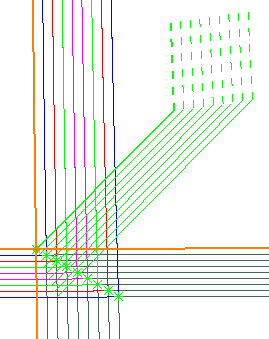
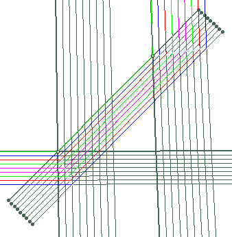
It is used to define a curve of minimum length (in green below),
with a given angle
that will initialize the new support curves (in pink
below):
It is the Grid Panel you want to process, the one you have
selected
when entering the Angle Cut Definition dialog box.
Defines the reference point (middle point on the green curve
below).
You can either select an existing point, or select two intersecting
curves.
When you select the last vertex, the two curves that intersect and
form
this vertex are used to populate the dialog box.
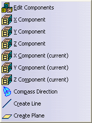
Defines the direction of angle cut computed from a rosette
transfer,
either by an angle or a direction.
Defines the minimum length of the curve (in green) that initializes the modified support curves.
Extrapol length 1 and 2
Define the extrapolation length on each side of the reference
point,
to define the end points of the minimum length curve.
Clicking Direction has the same effect as picking the arrows in
the 3D Viewer.
The number below show the correspondence between the pick and the result
on the direction:
![]()