-
Click Laser Projection Export
 in the Data Export toolbar.
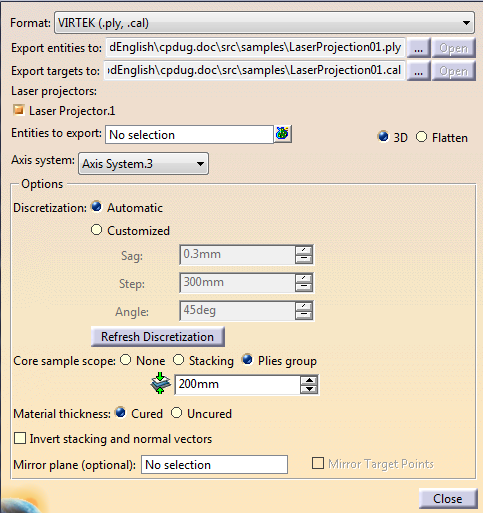
The Laser Projection Export dialog box is displayed:
-
Select the export format from the list (VIRTEK (.ply,.cal), LPT (.xml)), LASERGUIDE (.lg), LAP (.lpd, .cal).
-
Enter the storage path of the export files.
- Export entities to: defines the main storage path. Always required.
- Export targets to:
defines the storage path for
VIRTEK (.cal) files
when exporting calibration points.
It is automatically populated from the .ply storage path.
-
Optional: If you have selected an existing file, or generated one, click Open to check its content.
-
Select a Laser projector.
See Creating a Laser Projector for more information. Select an Axis system from the list.
The coordinates of the points in the export file are computed in this axis system.-
Set the options:
-
Optional: Select the Invert stacking and normal vectors check box to invert the order of the selected elements to export
(order of plies groups within the stacking, of sequences within plies groups, of plies with sequences, of cut-pieces within plies)
and the normal vectors associated to each discretization point.
This does not affect the elevation of discretization points since the core sample is performed with the actual stacking order. -
By default, 3D shapes of plies and cut-pieces are exported. Select Flatten to export the flatten shapes instead.
When Flatten is selected: - 3D contours, geometries in Additional Geometries Set, 3D stacking text directly under a ply or a cut-piece are ignored.
- Visible geometries and stacking texts created in a Flatten Body with option Taken into account by laser projection are taken into account.
- Stacking texts created outside Flatten Bodies with option Taken into account by laser projection are taken into account only if different from 3D type.
- Guide curves and order of drape geometries are not taken into account.
- Automatic texts are not generated.
- Core Sample Scope options are disabled as there is no elevation.
- Compute is disabled as there is no core sampling.
- The Flatten Body category of stacking text is ignored. When selected in the export preview, the text is displayed with a line type font, like other 3D stacking texts.
- Each visible geometry of a Flatten Body generates one item in laser projection and one per domain. Points and surfaces are ignored.
- The items are listen in the 2D
tree according to their category:
- Outer and inner contours are displayed as contours.
- Rosettes are displayed as Rosettes.
- Others are displayed as additional contours or curves.
-
Select the entities to export:
-
Multi-selection of entities
 and Stacking Management
 are
available.
are
available.
-
Entities can be the stacking, plies group, sequences, plies.
For plies with cut-pieces, only cut-pieces are taken into account. -
Plies groups with
heterogeneous support surface are supported, with a warning.
After a Compute, plies and cut-pieces that do not lie on the reference surface of the plies group are marked with a warning in the export tree. Computed elevation is displayed in the graphic area near each point.
The reference surface is the plies group engineering surface if used by some plies of the plies group, the manufacturing surface if used by some plies of the plies group otherwise, the most used surface otherwise. - Plies groups containing plies with different draping directions are supported, with a warning.
Selected entities are automatically discretized with the current discretization options.
The preview tree opens with elements to export and projectors.
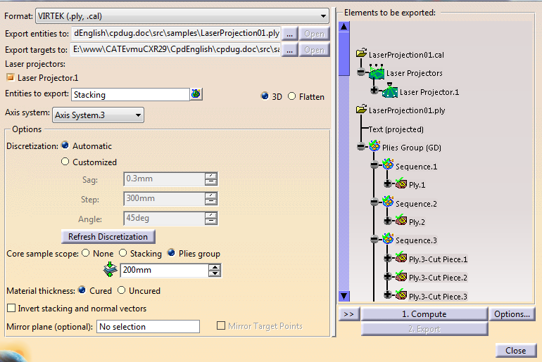
See About Laser Projection for details. -
Multi-selection of entities
-
If relevant, select a Mirror plane.
- Mirror entities are computed at once, by symmetry, with
feedback in the graphic area.
This feedback depends on the selected options. If Original Contours is selected, texts, additional geometries and rosette are displayed on both original and mirror parts, along with the initial contour on the original part. - To make them readable, stacking texts and automatically
generated texts are inverted after the symmetry.
The anchor point and direction of texts being a reliable reference for text location, they are mirrored.
The location of text within the ply shape may differ between the original and the mirror part. - For texts on multiple lines, the order of lines is kept.
- Clear the mirror plane selection to de-activate the option.
In addition, if a laser projector exists and is selected, select the Mirror Target Points check box to mirror them as well.
Be aware that laser projectors are not mirrored. As a consequence:
- To check the laser beam for the mirror part,
place the laser projector in a position that corresponds to
the projected mirror part.
If you leave the projector at the position chosen to project the original part, the beam will probably show incorrect results for the mirror part. - If you leave the laser projector on the original part side, select Mirror Target Points to mirror the target points.
- If you position the laser projector for the mirror part and its target points on the mirror part side, clear Mirror Target Points.
- Mirror entities are computed at once, by symmetry, with
feedback in the graphic area.
-
Under the preview tree, select Options and set the display options.
-
Select a node in the preview tree to check the discretization parameters or the elements to export.
This is a selection for check, not for export. -
Select a projector node to display the rays on the target points.
-
Optional: Double-click a projector node to edit the projector.
-
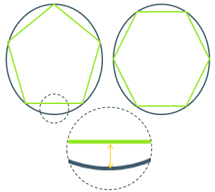
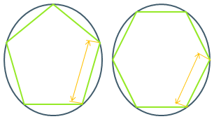
If the discretization is not satisfactory, edit the discretization parameters, click Refresh Discretization and perform another check.
-
Once you are satisfied with the check, click Compute.
The normal vectors are computed at each discretization point, and the points are elevated at their true position in space.
Review is still possible. -
Once you are satisfied, click Export.
If Compute is disabled, it means you have done no modification, and the computation is quick.
Otherwise, it will be longer as the normal vectors and elevation are computed anew.
The export files are generated.
![]()