For an easier use by cutting/nesting software, you can also generate a XML file that contains stacking information, such as order of plies, material and orientation.
This XML file also provides a link to each DXF or IGES file containing ply information, such as contours.
You can select only one export format (IGES or DXF), possibly completed by an XML file.
-
Select the required options in Tools > Options > Mechanical > Composites Design > Export Ply Data.
In particular, clear the Annotation option to avoid exporting both automatic and user-generated stacking texts, when both exist. -
Click Ply Data Export
 in the Data Export toolbar.
-
Select the format (DXF, IGES 2D or IGES 3D).
Only ply information is exported in those formats (for example, contours). -
Select the entities to be exported.
- Multi-selection of entities
 is
available.
is
available. - In the multi-selection
dialog box, click
 to select entities using the
Stacking Management.
to select entities using the
Stacking Management. - Select a ply, a ply
sequence, a plies group or a
stacking.
In our scenario, we selected the Stacking.
- Multi-selection of entities
-
Check the Export Stacking in XML check box to generate a XML file with stacking information and links to each DXF or IGES file.
It is stored under the same directory as the DXF or IGES file.
-
Click ... to select the directory where you want to store the export file.
-
Click OK to export the ply data.
The export files are created in the directory you have selected according to the selected Tools > Options.
Category Semantic is selected Graphic is selected Text or No category The text is exported as annotation
(Monospac821BT font)The text is exported as wireframe
from Monospac821BT fontOther categories The text is exported as polyline
(Laser projection font)The text is exported as polyline
(Laser projection font)
Stacking texts are exported in the DXF layer corresponding to their category, in a color depending on the Tools > Options.A report is generated. You can filter the messages:
- Exported: Lists all successfully exported files.
- Positioning: Lists the exported files where automatic
or user-generated stacking text postioning failed
(the text is not completely inside the flatten shape) and that need to be checked.
Be aware that there is no check if the Annotation check box is not selected in the Export ply data options. - Surface Error: Lists the files that were not exported or where issues exist.
- Unfold Assembly: Lists flattens computed with Unfold Assembly.
The name of the export file depends on the selected key words.
If identical names are detected, an increment is automatically added to the file name.If you open a .dxf or .ig2 file, a drawing is displayed
-
If you open an .igs file, a 3D curve is displayed.
-
If there is a text positioning error (DXF only):
- Select OK to continue the export with the text positioning as is.
- Or click Cancel to abort the export and correct the problem.
-
To correct the problem:
- Select the entity
in error, and Entity Preview.
It opens the same previewer as in Positioning Texts in the Stacking Management.
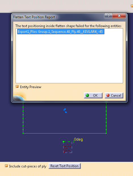
Proceed to required corrections. - Click OK in the message to proceed to the
export with the corrections.
Or Cancel to proceed to the export without the corrections (they will be lost).
- Select the entity
in error, and Entity Preview.
Manual positioning has priority over automatic positioning, until you select Reset Flatten Text.
![]()