This page deal with options concerning the export of ply data to DXF, IGES2D or IGES3D:
- File Name Pattern
- Export Mode
- Entities to Export
- Annotation Pattern
- Text Font for Stacking Preview
- Text Positioning
- Layer Options
- IGES 3D Contour Options
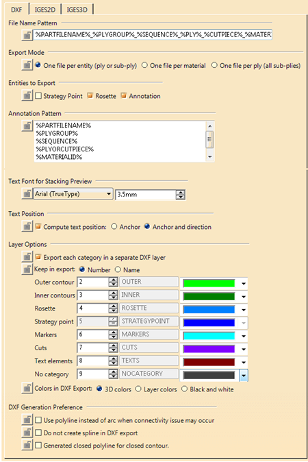
- Colors in DXF export
- DXF Generation Preference
These options are distributed in three tabs:
- DXF
- IGES2D
- IGES3D
They are listed below with the mention of the format to which they apply.
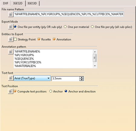
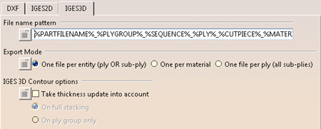
File Name Pattern (DXF, IGES2D, IGES3D)
Defines the name of the exported file using key words:
- %PARTFILENAME%
- %PARTNUMBER%
- %PLYGROUP%
- %SEQUENCE%
- %PLY%
- %CUTPIECE%
- %PLYORCUTPIECE%
- %MATERIALID%
- %MATERIALNAME%
- %DIRECTIONNAME%
- %DIRECTIONVALUE%
All characters are supported except /, \, ", :, *, ?, <, >, |, ° and any other character that is not supported in file names by Microsoft Windows.
If special characters are found in the values corresponding to the key word, they are replaced by “_“ e.g. 0/90 becomes 0_90.
Export Mode (DXF, IGES2D, IGES3D)
Possible export modes are:- One file per entity (ply or sub-ply): One file is generated for each ply or cut-piece.
- One per material: All plies or cut-pieces of the same material are exported in one single file.
- One file per ply (all sub-plies): The export file of the ply contains all the geometries of it cut-pieces, if any.
Entities to Export (DXF, IGES2D, IGES3D)
Defines the entities to export (Strategy Point, Rosette, Annotation)Annotation Pattern (DXF, IGES2D)
Customizes the annotations added to the flatten shape, using the same key words as for the file name:
- %PARTFILENAME%
- %PARTNUMBER%
- %PLYGROUP%
- %SEQUENCE%
- %PLY%
- %CUTPIECE%
- %PLYORCUTPIECE%
- %MATERIALID%
- %MATERIALNAME%
- %DIRECTIONNAME%
- %DIRECTIONVALUE%
Any other character can be added to the key words.
Add a carriage
return to write the annotation on several lines.
Text Font for Stacking Preview (DXF, IGES2D)
Defines the font family and size used exclusively for the stacking
preview.
When exporting to DXF/DWG, the font defined as default in the
Drafting standard applies.
This is not necessarily the one you use for
the preview.
Contact your administrator to learn which default font is
used, and possibly change it in the standard.
Text Position (DXF, IGES2D)
By default, the annotation is placed at the seed point (or a computed
central point) location
and written horizontally i.e. along the x axis of
the drawing view.
Therefore, in some cases the text does not completely fit
in the flatten shape of the ply.
Compute text position
attempts to keep the annotation inside the shape,
at the anchor location and
horizontally, or at the anchor location and along a direction.
Layer Options (DXF)
Defines the layers options:
- Separate elements in different layers exports the information of each category in a different layer.
Otherwise, several categories can be exported in the same layer. - Keep in export defines how the layers are driven, by their Number or by their Name.
- Patches of color define the color applied to the layer in the preview of the Stacking Management.
IGES 3D Contour Options (IGES 3D)
Take thickness update into account elevates the contours of the plies or cut-pieces by taking the thickness of the underlying ply into account:- On full stacking takes the sum of the thicknesses of all the plies below the ply to elevate into account.
To be used if the reference surface of the ply is not at the true location in space. - On ply group only takes the sum of the thicknesses of the plies below the ply to elevate, and that belong to its plies group, into account.