![]()
-
Click Transition Zone
 in the Preliminary Design toolbar.
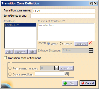
The Transition Zone Definition dialog box is displayed.
-
Select a zone in the specification tree or in the 3D geometry.
It is displayed in the Underlying zone field on which the transition zone lies.
A name is given to the Transition Zone that you can modify.
In our example, we changed the name to T1-1.
Note that you can select a zone group created with the For Solid From Zones Creation Only option. -
Define a contour by selecting curves so that they form a closed contour.
See Defining a Contour.
A green tip replaces the red cross.Use Insert After, Before and Remove to modify the order of the curves as well as the contour.
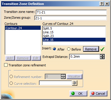

This contour must belong to the zone. -
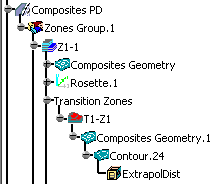
Click OK to create the transition zone.
The feature is displayed in the specification tree under the Transition Zone node.
- You can create several transition zones between two zones.
- The ExtrapolDist parameter is defined in the
Zone Definition dialog box.
It is stored under the contour of the transition zone.
-
Perform this scenario as many times as you need to create transition zones.
right-click in the Contour field and create the element you need.
|
|
Refer to Generative Shape Design & Optimizer User's Guide for more information.
![]()