- In braiding, the ply must be tubular, and limited by two boundaries. Composites Braiding checks that the ply surface has a tubular geometry, and that two contours exist and limit the ply.
- The braided ply references a braided material that contains the
nominal properties of the braid for a typical default status, defined as
a nominal braid angle of 45 degrees, and a braid separation equal to the
widths of the braid tows.
- Only the thickness has a meaning for the braided material. Other properties can be left at their default values.
- The constant nominal thickness of the braided material is used to visualize section and thickness update.
- The braid and axial tows of the braided material are referenced directly from the producibility parameters.
- The braiding simulation defines the continuously varying status of the braided material.
- The varying thickness is used to generate the detailed thicknesses, and thus the offset mandrel datum surface.
- The orientation defined for the current ply is the default braid angle, usually 45 degrees. You can create a "Braided" orientation, with a specific color, for an easy recognition of braided plies.
- The X-axis of the rosette defines the nominal centerline of the mandrel, used to define the start and end of the braid tube. The XY plane defines the reference plane to define the twisting of the mandrel.
-
Define the Composites Parameters.
-
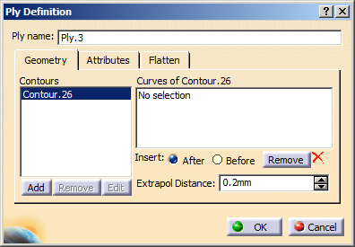
In the Plies Design toolbar click Ply
 and select either a sequence, a ply under a sequence or a plies group.
The Ply Definition dialog box opens.
-
Create the first contour.
- Right-click No selection under Curves of Contour.26 and select Create Extract in the contextual menu.
- Select the edge of one end of the mandrel tube.
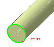
- Click OK in the Extract Definition dialog box.
-
Create the second contour at the other end of the mandrel tube.
- Click Add to add a contour.
- Create an extract as explained above, using the edge of the second end.
Go to the Attributes tab and select the Material, Direction, Rosette from the lists.
-
Click OK to validate and exit the dialog box.
- If you had selected a plies group, a new sequence is
created under this plies group.
It contains the created ply. - If you had selected a ply under a sequence or a sequence, the ply is created under the sequence.
- If you had selected a plies group, a new sequence is
created under this plies group.