|
-
Click Producibility for Braiding
 and select a ply with 2 loops.
See Creating
Plies for Braiding for more information.
Composites Braiding checks that the ply is tubular
and has one start and one end contour.
If the ply is valid, its name is
displayed in the dialog box.
-
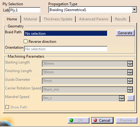
Select a Propagation Type
By default,
Braiding (Geometrical) is proposed.
-
Still in the Home tab, select the Braid
Path i.e. the travel path of the braiding head.
It is usually
the centerline of the components, and must be a single curve.
It must cover the entire surface, and even more to define a
starting and finishing length.- Either select an
existing braid path. Its name is displayed in the dialog
box.
- Or click Generate.
The
braid path is created as Centerline under a body
named after the ply, after the Stacking node.
The curve representing the braid path is smoothed to avoid
sharp bumps that reduce the quality of the resulting
braid.
The name of the braid path is
displayed in the dialog box.
The default values of the
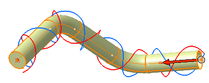
Machining Parameters are updated. - Select the
Show Path check box at the bottom of the dialog
box to display the braid head path as a pair of helices.
You can thus check
the consistency of the guide diameter and speed values.
Anticlockwise and clockwise tows are displayed in different
colors.
|
 |
It is very important to avoid sharp corners on the guide path. |
-
Specify an orientation curve that allows the rotation of the braiding tool
relatively to the component.
Selecting an orientation curve adds a head
angle in the speed table.
If you do not specify an
orientation curve, the Z-Axis is taken as the starting position of the
mandrel.
Optional: Select the Reverse direction check
box.
-
Enter the values of the Machining Parameters.
-
Starting Length: Distance before the
start of the ply, where the simulation starts.
Its
default value is 50 mm.
-
Finishing Length: Distance after the end of
the ply, where the simulation ends.
Its default value is
50 mm.
-
Guide Diameter: Internal diameter of the
guide.
Its default value is 1.5 times the Maximum
Diameter.
However, try to follow the practice of
manufacturing and use a guide ring that is a close fit to
the component. Using an overly large ring can cause
convergence issues with the solution on parts with
curvature.
-
Carrier Rotation Speed: Rotation speed of the
braiding machine.
-
Mandrel Speed: Average speed of the mandrel.
Either
- Enter a fixed value.
- Or click ... to specify variable mandrel
speeds.
|
-
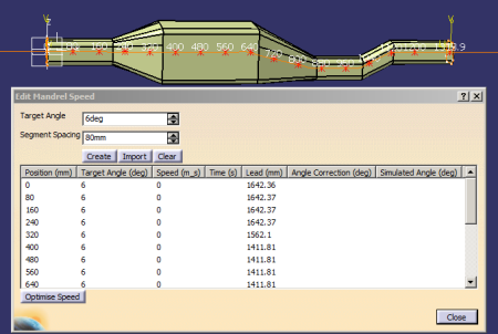
In the Edit Mandrel Speed dialog box
Editing the mandrel speed splits the braid axially into multiple segments, with a constant speed over each segment.
You can edit the position between each segment, defining the theoretical contact position on the surface.
-
Enter a Target Angle. By default it is the
ply angle, usually 45°.
-
Enter a Segment Spacing, i.e. the distance
between two consecutive segments.
-
Click Create to create the variable speeds.
Based on a calculation of the braiding simulation that
includes the effect of the lead of the carrier over the
contact point, a nominal speed is calculated analytically.
After a simulation is run, the average angle at each position
is calculated and the difference to the Target Angle
stored as an Angle Correction.
They are displayed in the 3D viewer and in the dialog box.
You can update the
Angle Correction column with the
results from the Results tab:
The difference
between the average simulated angle and the target angle is
used to estimate the correction angle.
- Click Import to import them from a xml or a csv file.
- Click Clear to erase existing values.
- Right-click anywhere in the table to add or delete rows.
- Once the speeds are created, click Optimize Speed.
Optimize Speed recomputes the speed by adding the
Angle Correction to the Target Angle.
Using this "reverse engineering" process, you can determine an
optimized speed profile to achieve an angle profile.
Checks are done to inform of possible problems and propose
actions.
|
-
Go to the Material tab to update material
parameters and click Estimate Thickness.
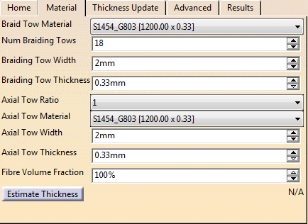
The complete braiding material consists of braid tows wound in a
clockwise and anticlockwise directions around the mandrel, and
optional axial tows.
By default, the braid tow material is
set to the material referenced by the ply, with the original
width and thickness appended to the material label.
The material
parameters of tow width and thickness can be overridden to
investigate the sensitivity of results to material parameters.
The number of braiding tows, typically between 18 and 36, is
half the number of carriers.
If the Axial Tow Ratio
is set to 1, the number of axial tows is equal to the number of
clockwise tows and equal to the number of anti-clockwise tows.
-
Braid Tow Material: Taken from the materials
defined in the Composites Parameters.
-
Num Braiding Tows: Number of braiding tows in
each direction, defined by the braiding machine, and equal
to half the carriers of the machine. By default, it is set
to 18.
-
Braiding Tow Width: Nominal cured width at
the expected fiber volume fraction.
By default, it is the
width of the selected material, but it is editable.
-
Braiding Tow Thickness: Nominal cured
thickness at the expected fiber volume fraction.
By
default, it is the thickness of the selected material, but
it is editable.
-
Axial Tow Ratio: Ratio of axial tows/braid
tows. Possible value are:
- 1 for tri-axial braid
- 0 for bi-axial braid (Axial Tow Material,
Axial Tow Width, Axial Tow Thickness are disabled).
-
Axial Tow Material: Taken from the materials
defined in the Composites Parameters.
-
Axial Tow Width: Nominal cured width at the
expected fiber volume fraction.
By default, it is the
width of the selected material, but it is editable.
- Axial Tow Thickness: Nominal cured
thickness at the expected fiber volume fraction.
By
default, it is the thickness of the selected material, but
it is editable.
-
Fiber Volume Fraction: Fiber volume
fraction to use to compute the thickness.
-
Estimate Dimensions:
Thickness information for cross-sections along the mandrel
is computed (minimum, maximum and mean values).
The
computation is based on the target braid angle, tow
dimension, number of tows and local perimeter of the
mandrel.
The range of perimeters is displayed, for an
early indication of the suitability of the design for use as
a mandrel in braiding.
|
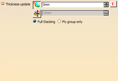
-
In the Thickness Update tab, select the
Thickness update check box to activate it.
It adjusts the height
of the surface to take underlying braid layers into account
(using the thickness defined for the material, not the effective one).
This is a quick method. For a
greater accuracy, use the mandrel generation tool.
It uses a thickness derived from braid simulations of the underlying layers.
In the Advanced Parameters tab:
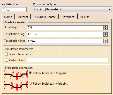
The braid calculation is done on a facetted mesh extracted from the
geometry.
The Tessellation Sag and Step control the
tessellation on which the simulation is run.
The Sag
represents the maximum distance from the surface to an element, while
the Step limits the maximum size of an element.
Fiber
Interaction invokes algorithms to account for the interaction
between fibers in an empirical way, stabilizing the simulation.
The
Centerline Orientation options force the guide to follow the
centerline, or to keep a constant alignment with the tangent at the
midpoint. -
Enter the required values:
-
-
Axial Step: Defines the maximum length of steps
when exporting the piecewise linear mandrel path curve.
-
Tessellation Sag: Distance between the mesh
and the surface used to generate the tessellation used in
the simulation and exported in the layup file.
-
Tessellation Step:
Maximum allowed length of an element used to generate the
tessellation used in the simulation and exported in the
layup file.
Setting a smaller value gives a better
approximation to the component shape, at the expense of
slower simulation.
-
Select the Fiber interactions check box to
check the interactions between fibers at each crossing point,
and reposition the fiber.
However, it is more time
consuming. Using this means that where fibers cross over other
fibers, they are pulled towards the surface.
- Select the Pertub Helix check box to compute perturbation
effects.
The braiding simulation assumes the fibre between the guide ring
and the mandrel is straight. However, the tow does not follow a
straight line from guide ring to mandrel, but a curved
(segmented) path due to the contact with the fibres going in the
opposite direction.
- With a cylindrical mandrel, this curvature
is the same at all points around the mandrel.
- With non-cylindrical mandrels the curvature varies, related in some way
to the distance between the mandrel and the guide ring.
A quick solution to the problem is to
calculate the amount by which the tow angles need to be adjusted
to account for the varying frictional affects when the mandrel
is not cylindrical based on the variation in number of fibres
crossed and use this to correct the fibre angles. A scaling
factor is added to tune the magnitude of the effect as it
depends on surface finish of the fibres, which is not accounted
for in the calculations. - If the check box is not selected or
if the value is 0, perturbation effects are not calculated.
- A
value of 1 uses the values as calculated.
-
Select the Centerline orientation, i.e. how the
brading machine is set up to work:
- Follow braid path tangent (default option).
Use this option if there is a large curvature on the mandrel
as a whole.
- Follow braid path midpoint: With this option,
the mandrel is translated without being rotated.
To be used
when there are sharp direction changes in the component,
causing the tow threads to overlap.
However, the total
change of direction of the centerline must remain small.
|
Click
Preview.

then go
to the Results tab to manage the
results.
Results are updated dynamically when input variables are
modified.
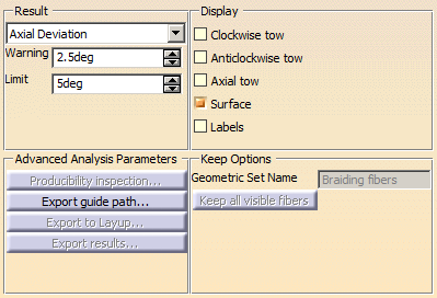 -
From the list, select the Result to check:
-
Axial Deviation
- Clockwise Deviation
- Anticlockwise Deviation
-
Clockwise Angle
- Anticlockwise Angle
-
Coverage
-
Separation
-
Thickness
-
Concavity
- Pertub Ratio allows
to adjust the scaling factor to get the desired effect
on large aspect ratio mandrels.
- Perimeter (Requires
Ruled surface Display).
- No Result
-
Define the Warning and
Limit
values.
- Warning defines the value for the yellow
band.
- Limit defines the value for the red band.
- Select the elements where the results are displayed (multi-selection is
allowed).
- Clockwise tow
- Anticlockwise tow
- Axial tow
- Surface
- Labels
- Ruled surface
|
Click
Producibility Inspection.
- Create points where you want to retrieve braided
fiber results.
Multi-selection is available.
- Click Apply.
Braided fiber results are displayed
in the Inspection Analysis dialog box.
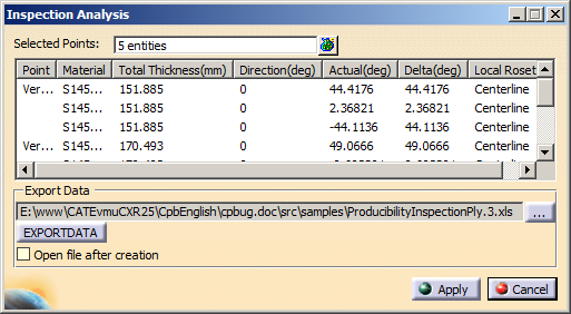
They
can be considered as core samples for producibility
results.
For each point, you can retrieve the material,
total thickness, expected and actual direction and the
delta between them, as well as the local rosette.
The
results can be exported.
|
Select an additional action:
-
Export guide path: Data from the centreline
and speed table are written to an XML file to drive
braid machines
-
Export to Layup: Writes out the standard
layup file that can be used to transfer Composites
definitions to other packages.
It creates a balanced
ply by writing 5 layers – ½ clockwise, ½ anti, axial, ½
anti, ½ clockwise.
Fiber directions are taken from
the simulated ones.
-
Export results as a .csv file for locations
along the guide path. The values are the average for a
ring of points at each location along the guide path.
- Inspect Angles
exports the variation in angle around the perimeter at a
chosen location on the mandrel to allow comparison of
simulation with experimental results.
- Select a point. It is projected onto the closest
point on the centerline.
- A plane normal to the centerline is created
at this point.
- A line is created at the intersection of the
plane with the mandrel surface.
- 100 points are created on this line.
- Or a line. 100 equally spaced points are created
on this line, then projected on the mandrel surface.
A set of 100 closest points is created on the
surface.
- Enter the storage path to export the result .csv
file.
- It looks like this.
Note: Point
gives the position of 100 evenly spaced points
around the perimeter.
|
Coordinate
|
Point
|
Ratio
CW
|
Ratio
ACW
|
Clock-wise
|
Anti-Clock-wise
|
Perturbed
Clock-wise
|
Perturbed
Anti-Clock-wise
|
|
(376.843
19.910 -13.811)
|
1
|
0.779
|
0.779
|
-48.002
|
45.82
|
0
|
0
|
|
(376.843
19.518 -15.228)
|
2
|
0.853
|
0.853
|
-46.544
|
45.975
|
0
|
0
|
|
(376.843
18.864 -16.544)
|
3
|
0.855
|
0.855
|
-45.38
|
46.107
|
0
|
0
|
|
-
Enter a name of a geometrical set, and press Keep
all visible fibers to do so.
The graphic lines used for the preview are
stored as geometrical lines, in three sets:-
Braiding fibers Clockwise tow
- Braiding fibers Anticlockwise tow
- Braiding fibers Axial tow
- Each set contains the lines, one for each
head.
|
-
When you are done, click OK to validate and
exit the command.
|