This task explains how to generate a flange from a spine and a profile.
For the Generative Sheetmetal Design workbench, open the NEWSweptWall01.CATPart document.
For the Aerospace SheetMetal Design workbench, open the Aero_SweptWall01.CATPart document.
Create a Flange without Support
-
Click Flange
 in the Walls toolbar (Swept Walls sub-toolbar).
The Flange Definition dialog box is displayed.
Note that the image in the right-hand pane of the dialog box is updated as you choose your parameters and options, and provides a graphical explanation about the current selection.
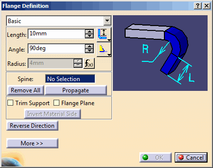

By default, the icon which is pre-selected next to the Angle field corresponds to an acute angle  for the Generative Sheetmetal Design workbench, and to an obtuse
angle
for the Generative Sheetmetal Design workbench, and to an obtuse
angle  for the
Aerospace SheetMetal Design workbench.
for the
Aerospace SheetMetal Design workbench. -
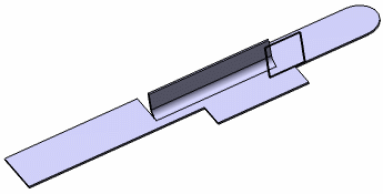
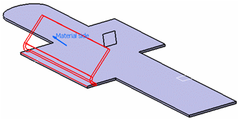
Select the edge as shown in red.
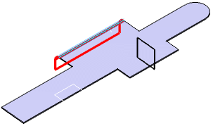
The Spine field is updated with the selected edge.

-
You can use the Remove All button to remove the selected edges.
-
You can use the Propagate button to select all tangentially contiguous edges forming the spine.
-
-
Select the flange type:
-
Basic: the flange is created along the whole support (as in our scenario)
-
Relimited: the flange is created within limits you define on the support (points, for example). Refer to More about the Relimited Flange.
-
-
Choose the flange parameters:
-
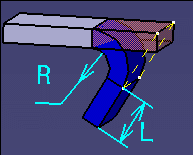
Enter 15mm in the Length field. Use the icons
 next to the field
to specify the type of length. Note that the length is always computed
using the lowest external point of the flange.
next to the field
to specify the type of length. Note that the length is always computed
using the lowest external point of the flange. -
Enter 45deg in the Angle field. Use the icons next to the field to specify whether the angle is acute
or obtuse .
-
-
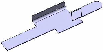
Optional: Click the Reverse Direction button to reverse the direction of the flange.
-
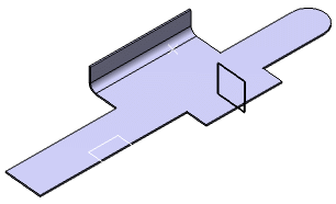
Click OK to create the flange.
The flange is created and the feature is added to the specification tree.
Create a Flange with a Support
-
Click Flange
and select an edge. -
Select the support type:
-
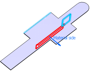
Optional: Click the Invert Material Side button to reverse the material side.
-
Optional: Click the Reverse Direction button to reverse the direction of the flange.
This option is only available when the Trim Support or Plane Support check box is selected, otherwise it is deactivated. -
Click OK to create the flange with a support
Trim Support
Plane Support


More about the Relimited Flange
Selecting Relimited updates the dialog with two new fields (Limit 1 and Limit 2) to let you specify the flange limits.
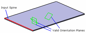
You can then select as the limits two points, two planar faces, a point and a planar face, or a point and a vertex, as shown below, for example.
Note that right-clicking in the Limit 1 and Limit 2 fields lets you create the limits (points, plane) or choose the X, Y or Z plane on-the-fly.

More about the Bend Allowance
Click the More button to display the Bend Allowance tab allowing you to locally redefine the bend allowance settings.
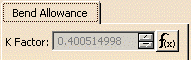
The value defined for the K factor in the Sheet Metal Parameters is used as the default value. Note that according to the DIN standard, if the radius is modified, the K factor is adjusted accordingly.
You may need to deactivate the formula using the contextual menu on the field and choosing Formula > Deactivate before editing the value.
In this case, the new K Factor value overrides the value set in the Sheet Metal Parameters.
A preview of the flange to be created is displayed in the geometry area.
![]()