 |
This task explains
how to generate graphic replacement for stiffeners. |
 |
The sample XML file provided with this application is
Structure_GVS.xml.
This file is located in ../OS/resources/standard/generativeparameters.
Customizing parameters in this file affects the appearance of your
drawings and is an administrator task. The reference
planes that will be used for a given project are defined in an XML file
pointed by a PRM
resource:
- ProjectReferencePlanes.
For more information, see
Project Reference Planes. |
 |
Appropriate application
licenses including one for Generative Drafting are required. |
 |
For information on how to create views using generative
view styles, how to set view style parameters or more generally on
administering generative view styles, see the Generative Drafting
User's Guide. |
|
|
For graphic replacement for reference plane systems,
see
Graphic Replacement
for Reference Plane Systems.
|
 |
In the sample XML file, generative view style parameters for
stiffeners are located
towards the bottom of the file under StructureObjects.
|
|
|
- Stiffener
-
- Draw Values
- Graphic Replacement
Values
-
- Angular Tolerance Values
-
- ViewType Description
-
- TopView
-
-
- NearSide
Parameters
- FarSide
Parameters
- Acrosside
Parameters
-
AnnotationTextStyle
Parameters
-
-
- FlangeOrientationSymbol
Parameters
- ExtremitySymbol
Parameters
- MaterialExtrusionSymbol
Parameters
-
-
- SideView
-
-
-
- NearSide Parameters
-
-
-
- FarSide
Parameters
- Acrosside
Parameters
-
AnnotationTextStyle Parameters
-
-
-
- ExtremitySymbol
Parameters
- SlotSymbol
Parameters
-
FlangeLine Parameters
- WeldSymbol
Parameters
-
-
- EndView
-
-
-
- NearSide
Parameters
-
-
-
- FarSide
Parameters
- Accrosside
Parameters
-
AnnotationTextStyle
Parameters
-
-
- AnyView
-
-
-
- NearSide
Parameters
-
-
-
- FarSide
Parameters
- Acrosside
Parameters
-
AnnotationTextStyle Parameters
-
|
|
|
Draw Yes extracts the
object.
No indicates the object will not be extracted. |
|
|
GraphicReplacement Indicates
whether to use graphic replacement. Yes or
No. |
|
|
Angular Tolerance To trigger
this type of view in degrees. Default is 15.0. |
|
|
ViewType There are four view types
for stiffeners: TopView, SideView, EndView
and AnyView.
Each has NearSide, AcrossSide and FarSide
parameters and
AnnotationTextStyle
Parameters.
Additionally, TopView has:
SideView
also
has ExtremitySymbol
parameters.
Note: Logical and Functional Tolerancing and Annotation (FTA) Section
are the only modes, where you can compute AcrossSide parameters, which
are similar to NearSide and FarSide
parameters. The default
values are same as NearSide values. If you are not interested in an
AcrossSide analysis, you need to synchronize Near and Across
Linetype and LineThickness.
|
|
|
FlangeOrientationSymbol
- Draw
- To draw a flange orientation symbol at the ends of a stiffener.
Default is Yes.
- ChapterName
- The name of the chapter containing
FlangeOrientation symbols within the Drawing Symbol Structure Catalog.
(Refer to PRM file.)
- SymbolName
- The symbol name to draw.
- ReferenceScale
- Scale factor to apply to the symbol as drawn. Default is
1.
- SymbolLocation
- The location on the line representation of the plate where the
throw orientation will be drawn. Values are:
- 1 Start
- 2 Middle
- 3 End
The following shows a stiffener in TopView FarSide
with a SymbolLocation of Start.
The following shows a stiffener in TopView FarSide
with a SymbolLocation of Middle.
 |
|
|
ExtremitySymbol
- Draw
- Indicate Yes to draw arrowheads at the extremities.
No is the default (arrowheads are not drawn.)
- MinimumLengthRatio
- A percentage of the length of the stiffener used to determine if
there is enough room to draw the extremity symbols without overlap.
The default is 45. In other words, the length of the
symbol placed at an extremity may not exceed 45% of the total length
of the stiffener, taking into account the ReferenceScale and the
view scale.
-
ReferenceScale
- Scale factor to apply to the symbol as drawn. Default is
1. (A value of 2 results in a placed symbol twice
as big.)
- ChapterName
- The name of the chapter containing
extremity symbols within the Drawing Symbol Structure Catalog.
(Refer to PRM file.)
-
DefaultExtremitySymbol
- The default symbol used to represent the end of a stiffener
without endcuts.
- ExtremitySymbolByEndCutType
-
- Draw
-
- Indicates stiffener end symbol is
dependent on the end cut type (Yes). No
(default) indicates the
SymbolsAtEndsOfProfile option will always be used.
-
- Snipe
- The symbol used for a Snipe endcut.
- Weld
- The symbol used for a Weld endcut.
- Trim
- The symbol used for a Trim endcut.
The following shows a split stiffener in TopView with an ExtremitySymbolByEndCutType
of Snipe and Trim endcuts.
The following shows a split stiffener in SideView with an ExtremitySymbolByEndCutType
of Snipe and Trim endcuts.
|
|
|
MaterialExtrusionSymbol
- Draw
- Draws the material throw orientation. Yes or No.
- MaterialExtrusionMode
- Draws the material throw orientation. Values are:
- 1 Tick mark (true width)
-
- 2 Throw orientation (symbolic)
-
- 3 Tick mark and throw orientation
-
- SymbolLocation
- The location on the line representation of the plate where
the throw orientation will be drawn. Values are:
- 1 Start
- 2 Middle
- 3 End
- MaterialThroughOrientationSymbol
-
- ChapterName
-
- The name of the chapter containing material through
orientation symbols within the Drawing Symbol Structure
Catalog. (Refer to the PRM file.)
-
- SymbolName
-
- The symbol name to draw.
-
- ReferenceScale
-
- Scale factor to apply to the symbol as drawn. Default is
1.
-
- TickMarkSymbol
-
- Length of tick mark when drawing a tick mark. Default is
5.0 millimeters.
|
|
|
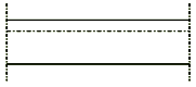
FlangeLine
- Draw
- Draws the flange representation. Yes or No.
- OffsetMode
- The offset mode to specify the offset value of the line.
Absolute or Relative.
Default is Relative.
- OffsetValue
- Offset value of the line representing the flange from the flange
top surface.
In Absolute mode, you can specify the offset value in mm.
In Relative mode, you can specify the offset value in
fraction. Maximum is 1.
The following shows a stiffener in NearSide View :
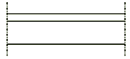
The following shows a stiffener in FarSide View :
|
|
For free edge stiffeners, only mechanical projection is
available for all kinds of views. |
|
 |
WeldSymbol
The following shows the weld symbol for stiffener.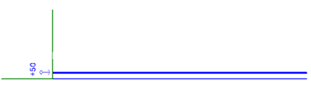
|