-
Click the Templates tab.
The base plane (in white) and a red vector indicating the direction in which the base plane will be offset are shown in the geometry area. The red vector identifies on which side of the plate the templates will be located.
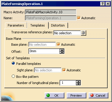
You can create either a set of parallel templates or a box-like pattern of templates. In this scenario, you will create a set of parallel templates.
-
Click the Transverse reference planes field and select the transverse planes you want to use as reference planes in the geometry area.
If a plane does not intersect the curved plate, no template will be created at this location. -
If desired, clear the Automatic check box opposite Base plane, click the Base plane field and select a plane in the geometry area.
The system automatically computes the base plane from molded surface points using the least squares method.
The base plane is shown in the geometry area alongside the direction of extrusion and offset vectors. -
Specify an offset for the base plane to adjust the height of the final templates, for example 2000mm.
Note: You must enter a positive value. The Change step command in the contextual menu of the Offset field lets you enter a different increment by which the field is updated.
The red vector showing the direction in which the base plane will be offset and the offset value are shown in the geometry area.
-
Select Parallel templates or Box-like pattern depending on the type of set you want to create. In this scenario, keep Parallel templates.
-
If you select Parallel templates, the system defines the sight plane. To select your own sight plane, clear the Automatic check box, click the Sight plane field and select the desired plane in the geometry area.
The sight plane is the plane through the mid-points of the first and last template location lines. It is orthogonal to the base plane and may be orthogonal to the templates.
-
If you select Box-like pattern, specify the number of longitudinal planes to define the longitudinal templates. One to three longitudinal planes are typically selected.
-
-
Click the Add button.
The Tools Palette appears, which enables you to select one or more segments of any number of curves on a curved plate. For example, you can select the segments of a curve, segments of attachment line, and segments of all the four edges in one shot. -
Select the curves you want and click Finish
 in the Tools Palette.
 -
Click OK in the Plate Forming Operation dialog box.
Requested roll line items and templates are created. In addition, the system distinguishes between the segments and corresponding parent curve, and generates a manufacturing item called a Distortion Curve Item for the parent curves under plate forming operation. This item holds the information about the selected curve and corresponding selected segments under that curve. To review the data, see Extracting Inverse Bending Curve and Plate Distortion Data in an XML File.

Templates are resources and as such are stored in a CATPart under the ResourcesList node in the PPR tree. The CATPart contains the skeleton geometry for the templates, each template being in a separate body. Templates are also identified under the Resources node of the appropriate operation.
To modify any templates that have been created, they must first be deleted from the ResourcesList.
-
Update the in-process model (using the IPM Update command).
-
Click Preview to view the IPM part corresponding to Shell_STB_1.
The curved shell plate is flattened and a flat plate obtained. Note that the IPM part contains all the necessary features for the downstream forming operation: roll lines, template location lines, sight lines as well as attachment lines and any added material on free edge.
-
Edit the plate forming operation and change the distortion and the neutral axis position, then update the in-process model and view the IPM part again.
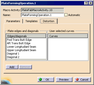
The selected curve appears in the User selected curves list.
![]()